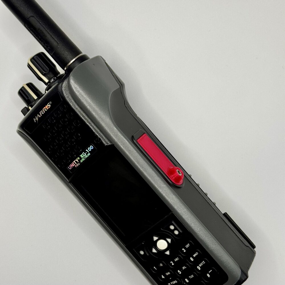
File to make it yourself: XG-100P-AccCover-v6.stl
Hardware needed: M3x6 hex cap screw
File to make it yourself: XG-100P-AccCover-v6.stl
Hardware needed: M3x6 hex cap screw
Finding the device ID for Exchange when you use the native mail app for iOS is fairly straightforward, but if you use the Outlook for iOS app, it is much harder to find.
I’ve discovered a process to uncover the device ID, because it appears to be hidden from the Outlook app alltogether.
See this screenshot from an Outlook App device in Exchange Online. Compare it to the one below it of a device added with the native mail app.
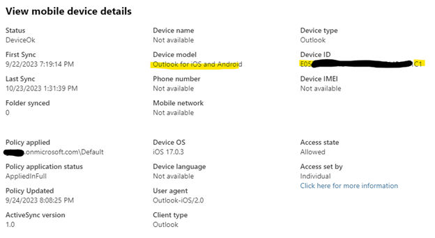
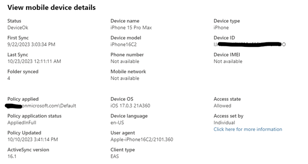
The native mail app gives you more detail, which can help you identify the correct device easier. The Outlook app has almost no information besides the iOS version which is usually outdated.
We can get the device ID from your device that uses the Microsoft Outlook App, but you need to perform some additional steps.
You will need a Windows PC with the Microsoft store to download the Microsoft Diagnostic Data Viewer The mobile device in question must be connected to the same Wireless network as the diagnostic PC. The outlook app will create a TCP connection to the PC to send logs.
Download Microsoft Diagnostic Data Viewer on PC
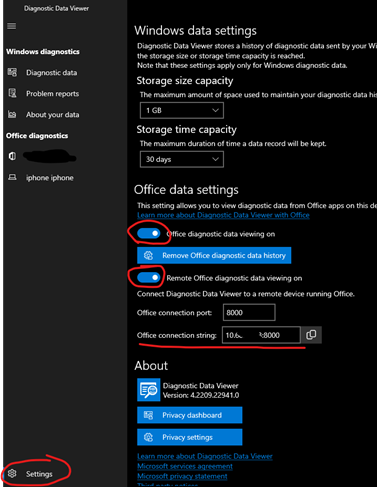
Go into Settings and enable Office diagnostic data viewing on, and Remote Office diagnostic data viewing on
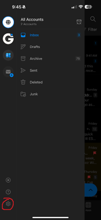
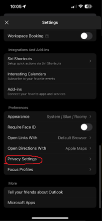
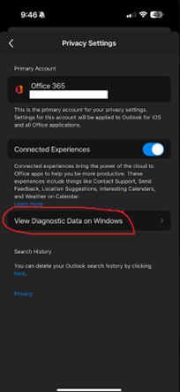
Open the Outlook App and go into Settings>Privacy Settings>View Diagnostic Data on Windows
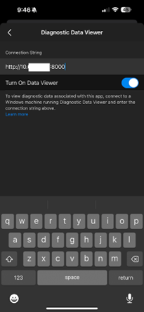
Copy the Office Connection String from the Diagnostic Data Viewer, and enter it into the Connection String field on the Outlook App.
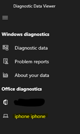
Exit back to the main screen of Outlook, and check for new messages by pulling down on the Inbox screen. You should see your mobile device show up on the sidebar of the Diagnostic Data Viewer
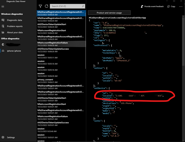
Select this device, and you should see JSON debugging information. This localId matches what we see in Exchange Admin Center
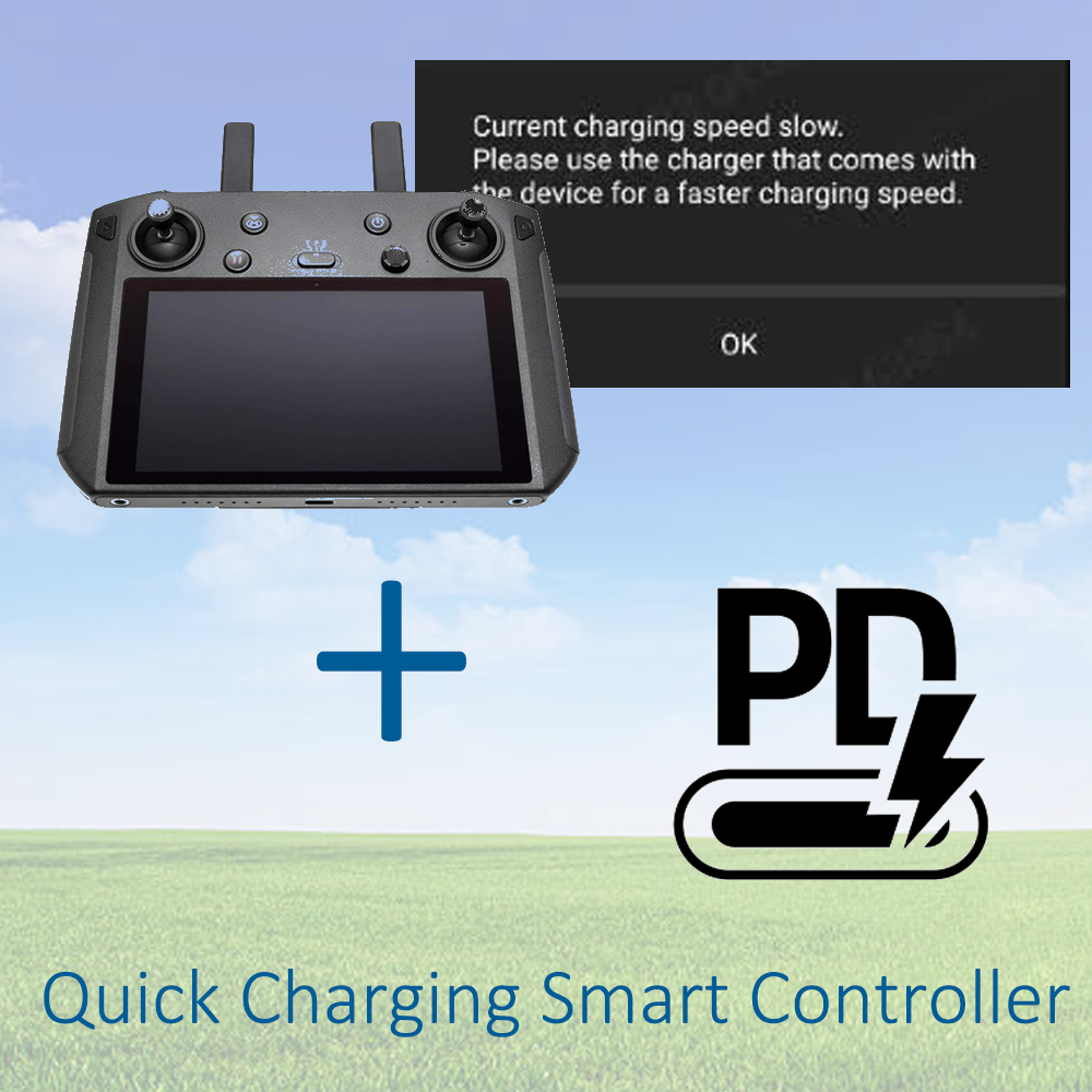
If you own a DJI Smart Controller, you may have come across this message while trying to plug it in to charge.
Current charging speed slow. Please use the charger that comes with the device for a faster charging speed.
Slow charging a smart controller could represent a hazard, because the slow charge rate isn’t enough power to maintain the battery level while flying your drone.
After a recent incident where the smart controller shut down while I was flying a drone, I became determined to find a solution to be able to rapid charge the controller via a battery pack I already had
A forum post I discovered mentioned the controller used Qualcomm’s QuickCharge standard. Qualcomm’s QuickCharge standard is a pre-USB PD era charging standard that allows negotiated charging above 5v for supported devices.
I didn’t want to buy yet another battery pack just for an antiquated standard, so I opted to make a cable that converts USB PD to QC instead.
Parts list (Amazon Affiliate links):
Consumables I already had:
Tools:
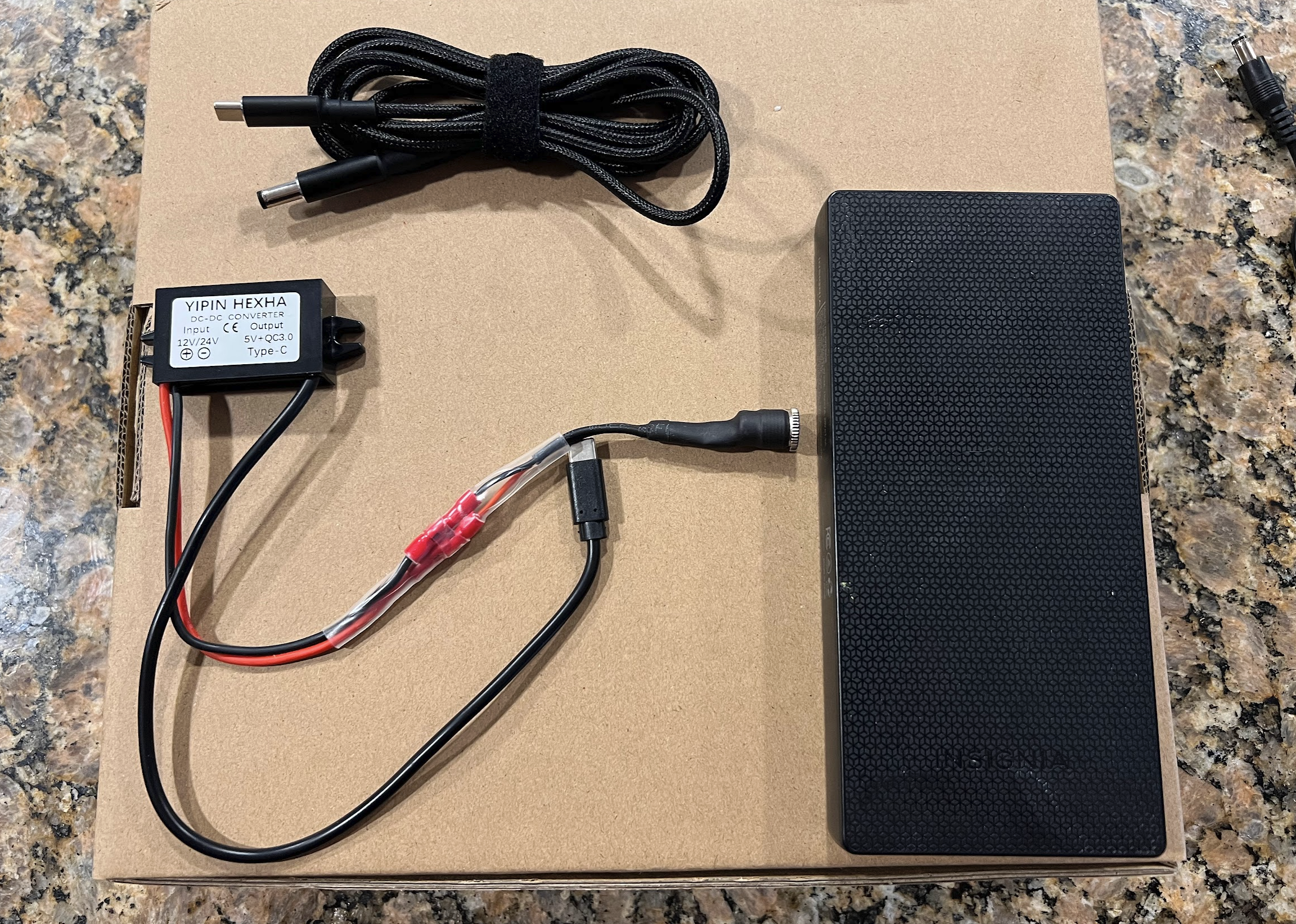
Here is the final product:
The braided cord goes into the battery pack, and the barrel plug goes into the QC 3.0 adapter. This braided cord is the magic sauce that tells the charger to output 20v, and send that to the “yipin Hexha” adapter
That adapter will let you charge your Smart Controller significantly faster than before, and your controller won’t die while charging. Hope this helps!

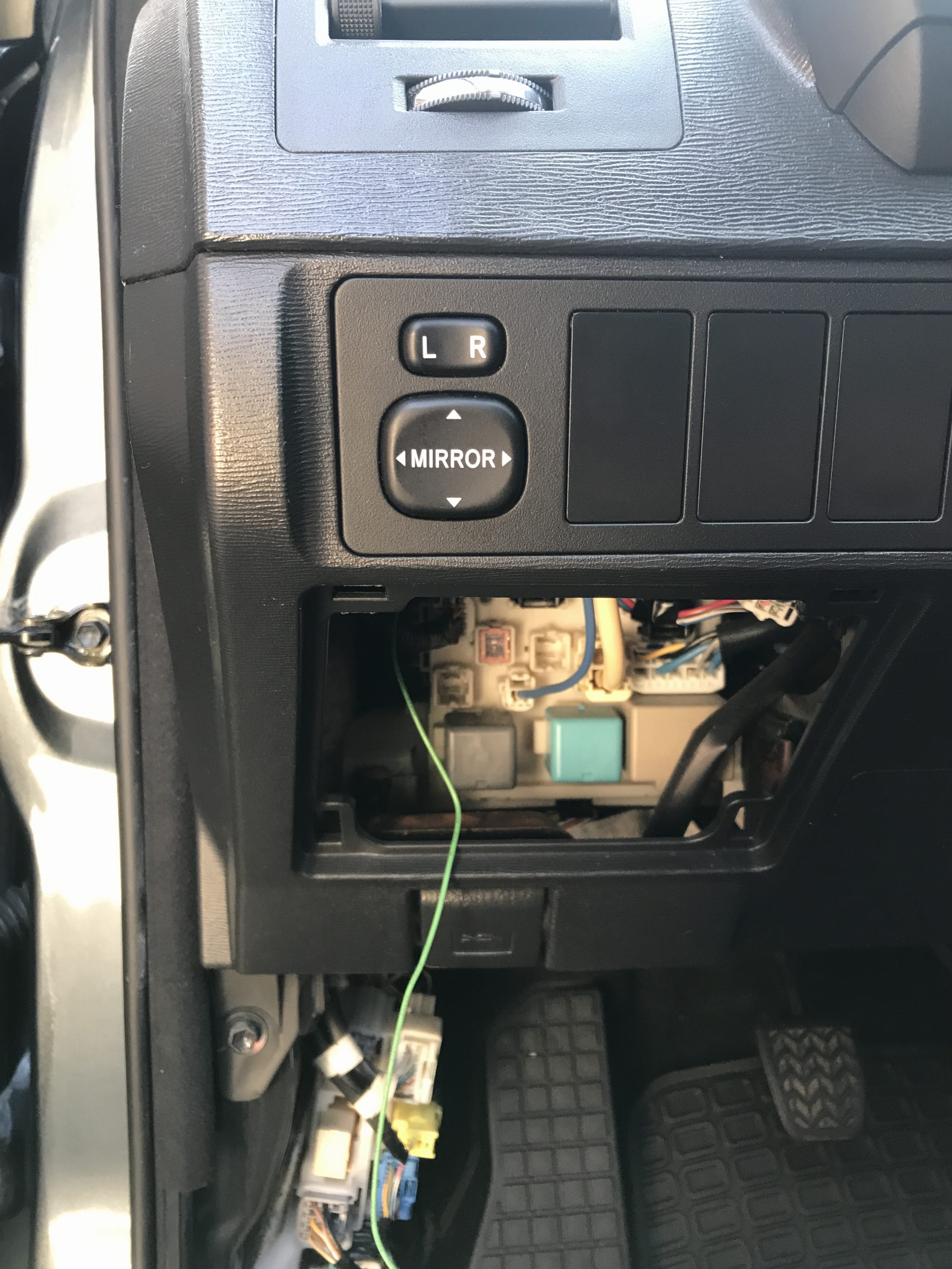
This guide will show you the fuse locations and equipment needed to hardwire a radar detector or dashcam on a 2022 Hyundai Elantra N
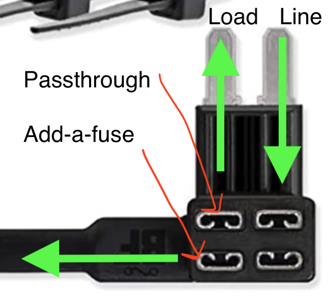
Consumables needed: Micro2 Fuse Tap (Affiliate Link)
Note: Fuse Taps are directional! For unpopulated fuse banks, only put a fuse in the top and leave the passthrough spot empty.
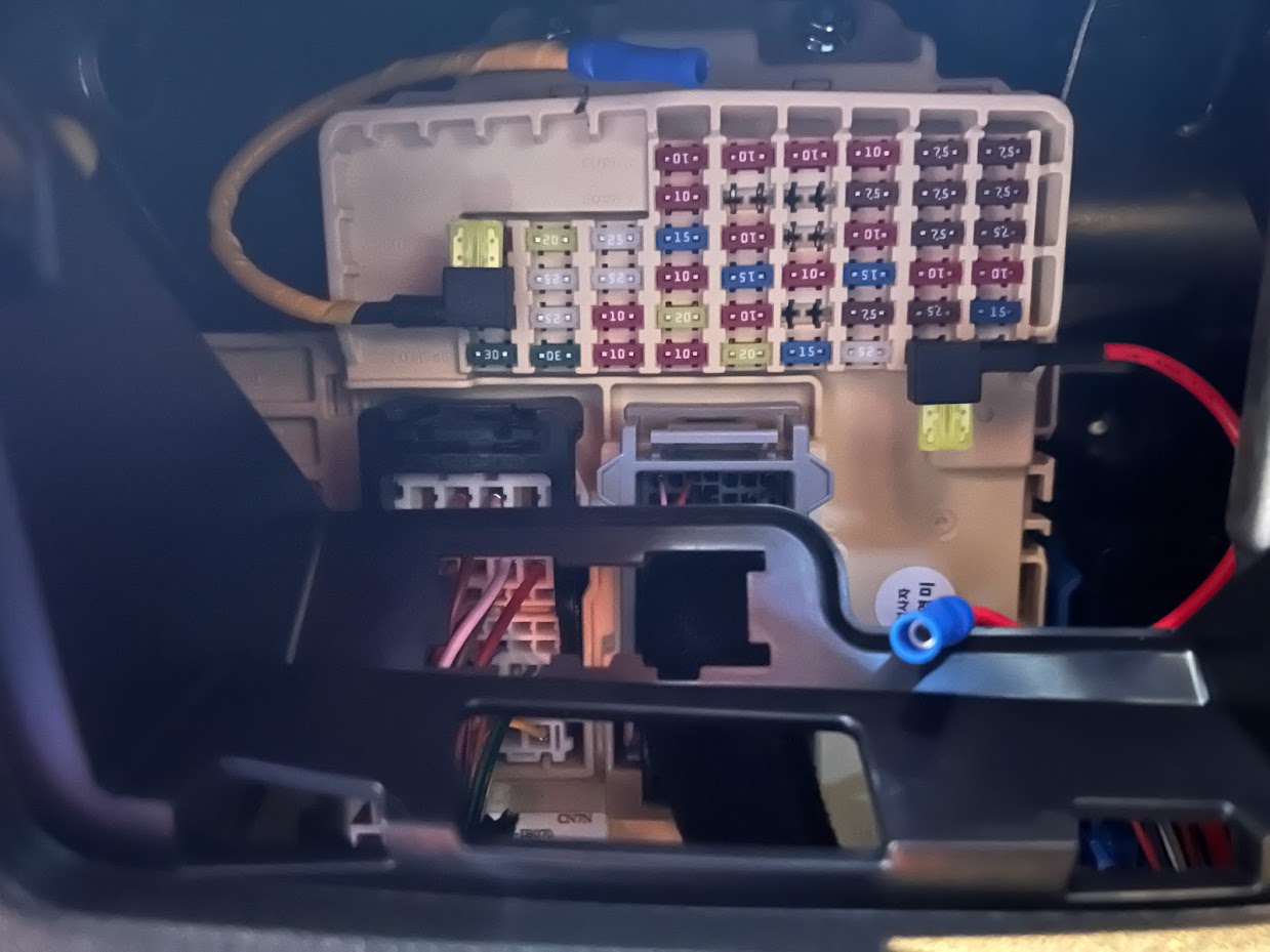
Fuse Locations
Fuse 47 (red wire on right) should be unpopulated. The left side will provide +12V when the car is on. Insert the fuse tap with the fuse facing down. You can use this for Radar Detectors, Remote wire for amp turn on, Dashcam, etc.
Fuse 31 (yellow wire on left) will provide the car +12v at all times. You can use this for parking mode wire
Ground Location
To allow an Allworx phone system to receive updates the following IP’s must be unblocked:
allworxportal.com (52.191.116.193)
TCP/8081
TCP/80

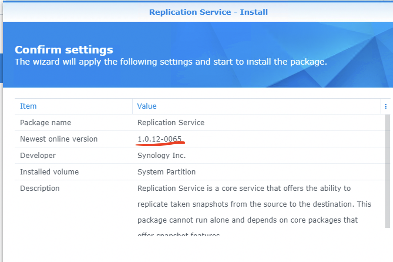
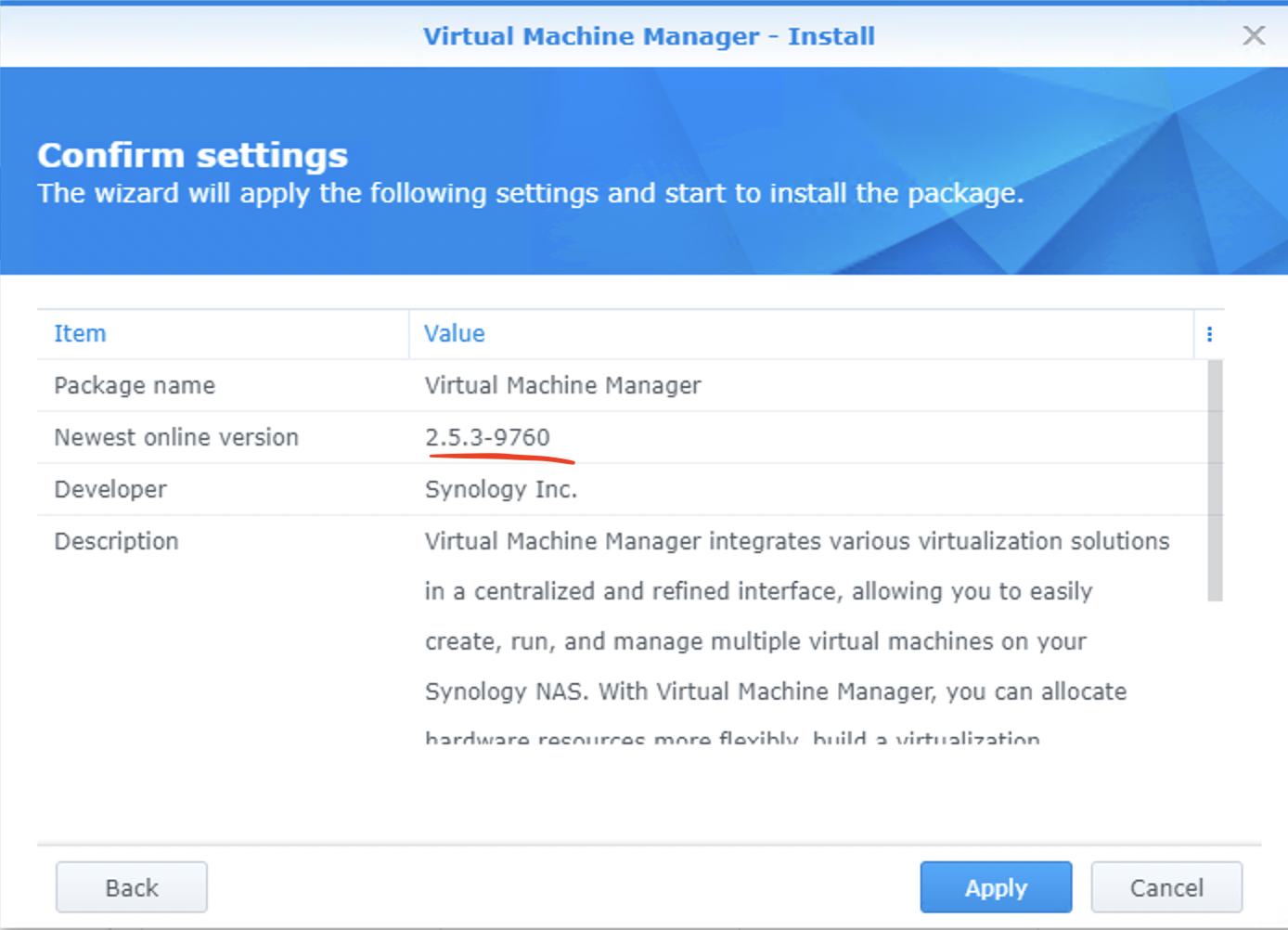
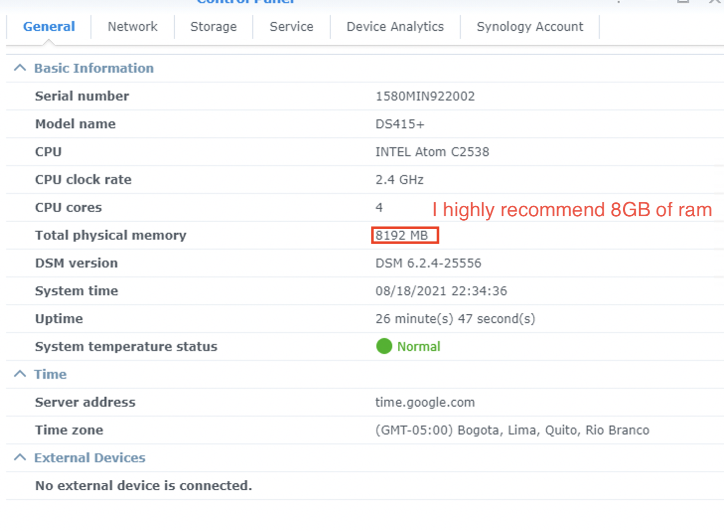
I haven’t seen anyone successfully get VMM working on an upgraded DS415+ with 8GB of RAM.
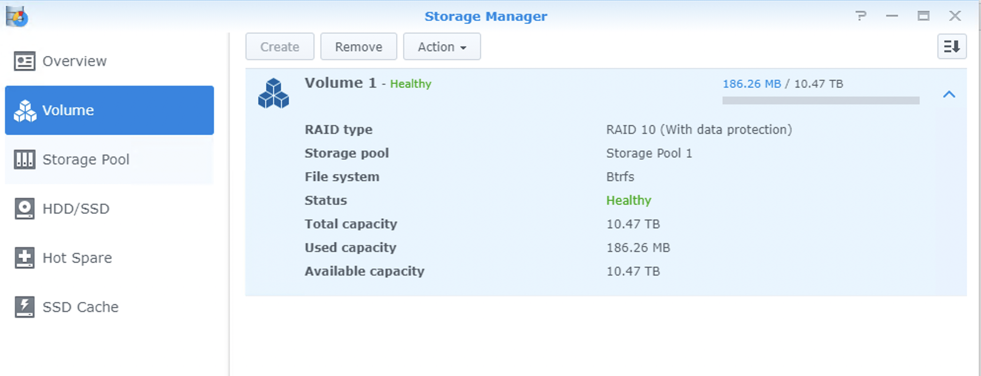
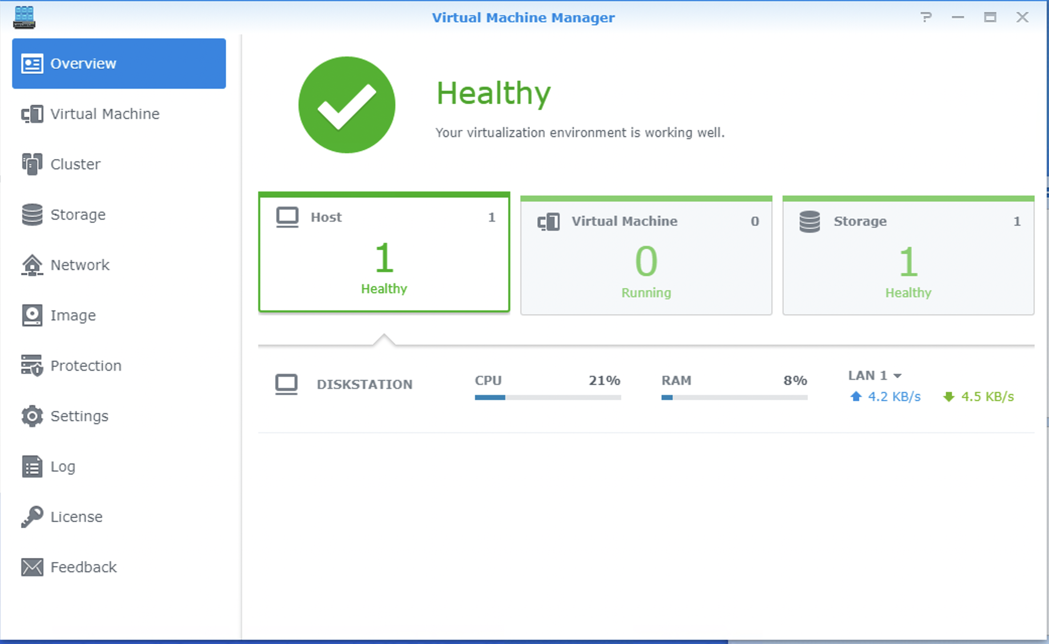
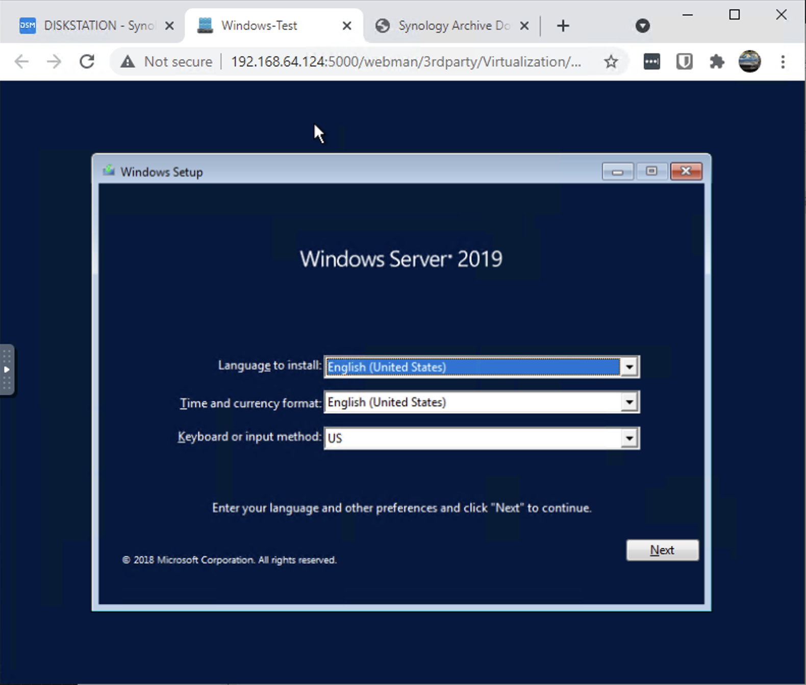
Yes. It IS possible. You have to use specific version of packages found at: https://archive.synology.com/download/Package/
Replication Service: 1.0.12-0065
Virtualization: 2.5.3-9760
I’m running DSM: 6.2.4-25556
Photos below:
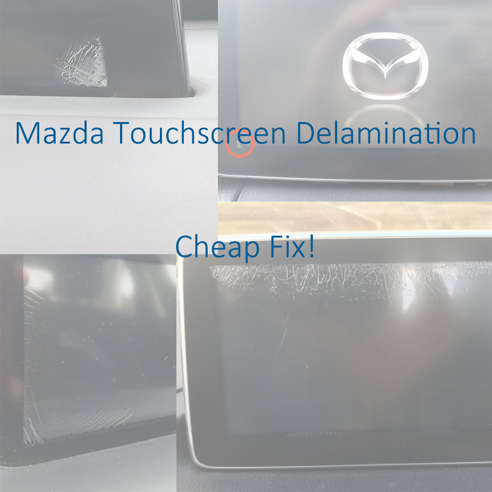
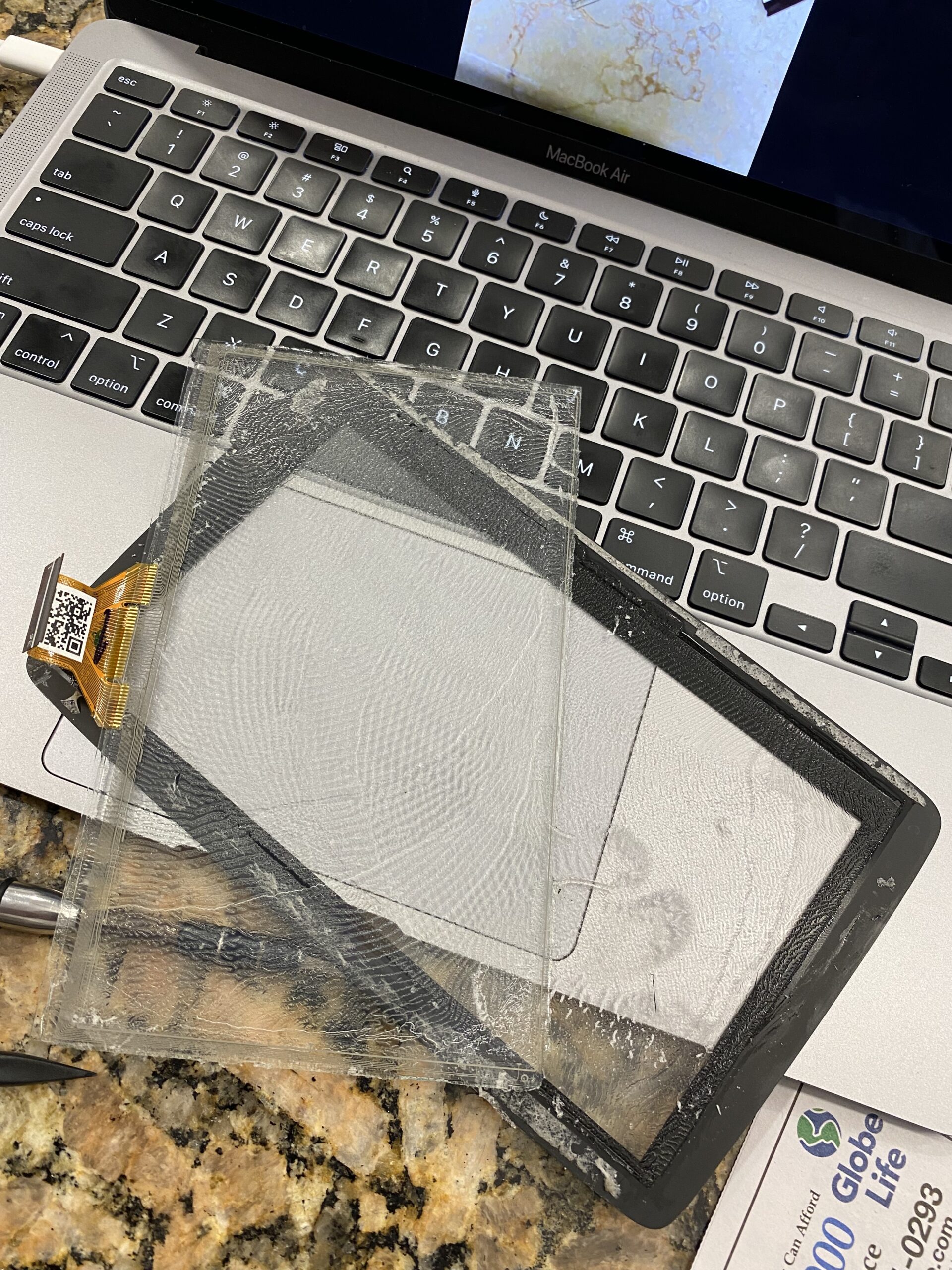
If your Mazda Connect screen has developed cracks, ghost touch issues, or random touchscreen behavior, you may be able to fix it without replacing the entire CMU or screen assembly.
This repair uses basic tools and an inexpensive replacement digitizer, typically around $15–$25, making it far cheaper than a dealership repair or full screen replacement.
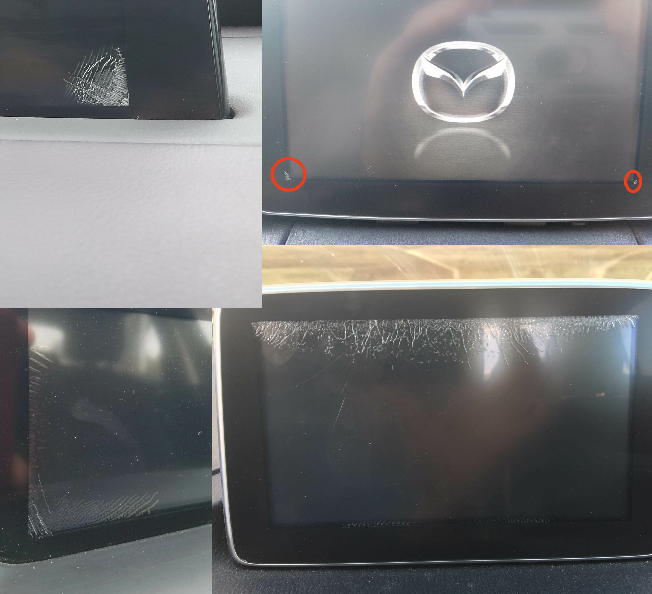
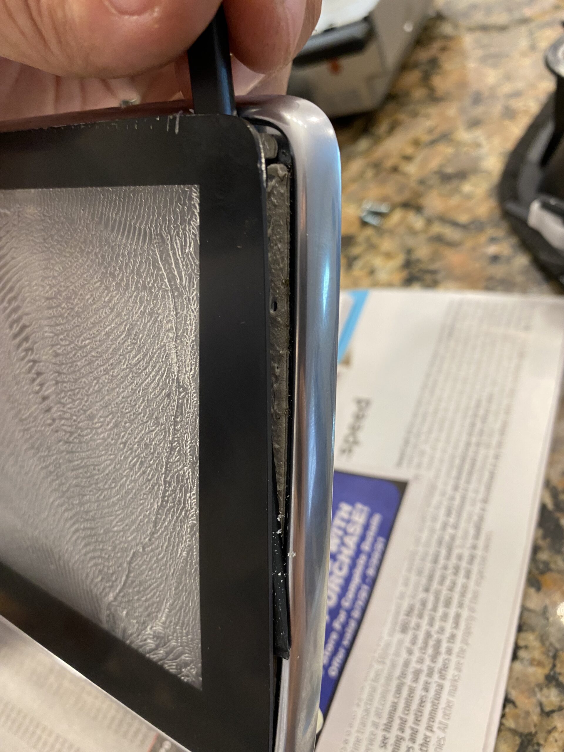
This issue is usually caused by adhesive delamination between the touchscreen cover and the digitizer after repeated hot and cold cycles.
If your vehicle is still under full warranty, Mazda may replace the unit at no charge.
View Mazda TSB / warranty information
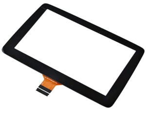
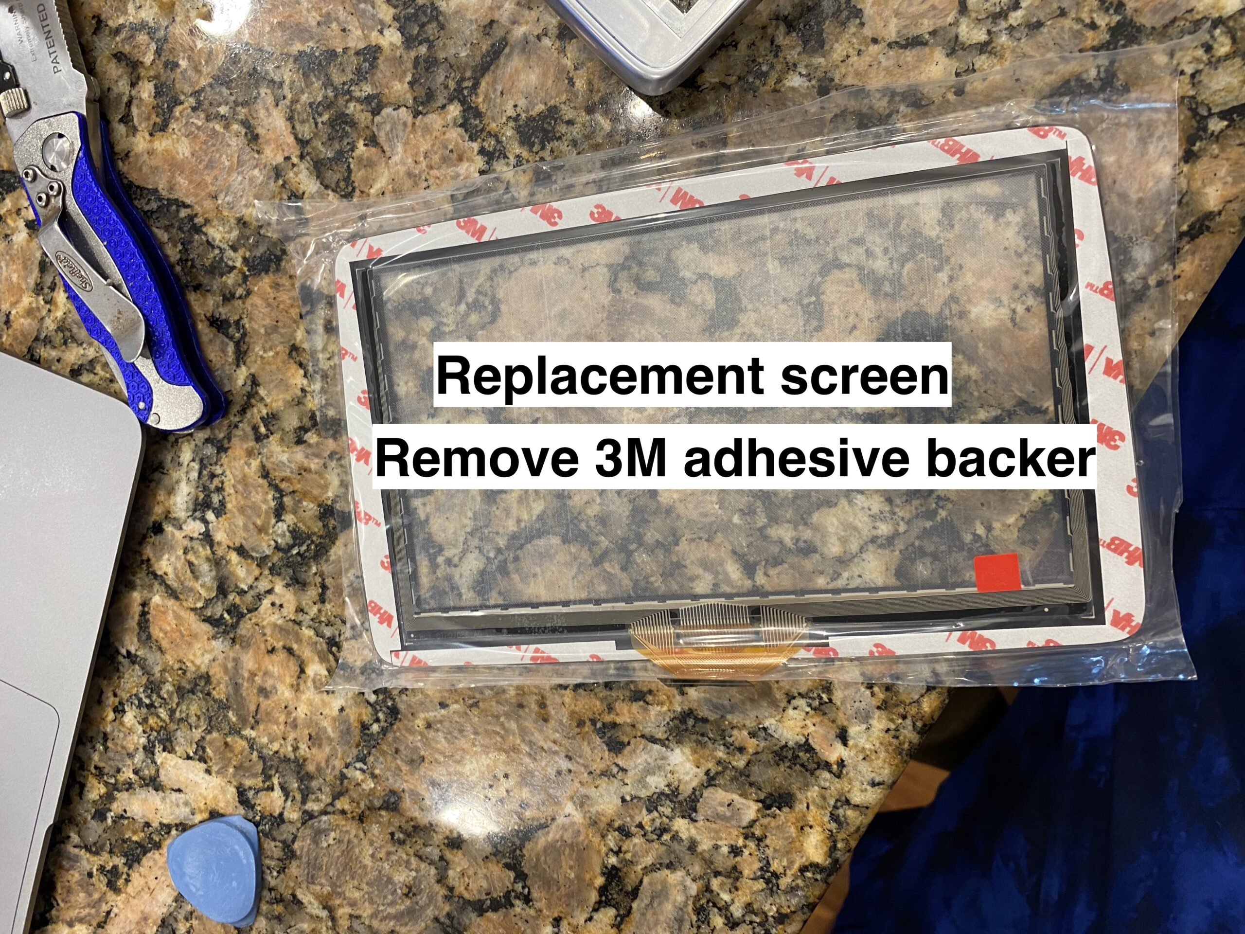
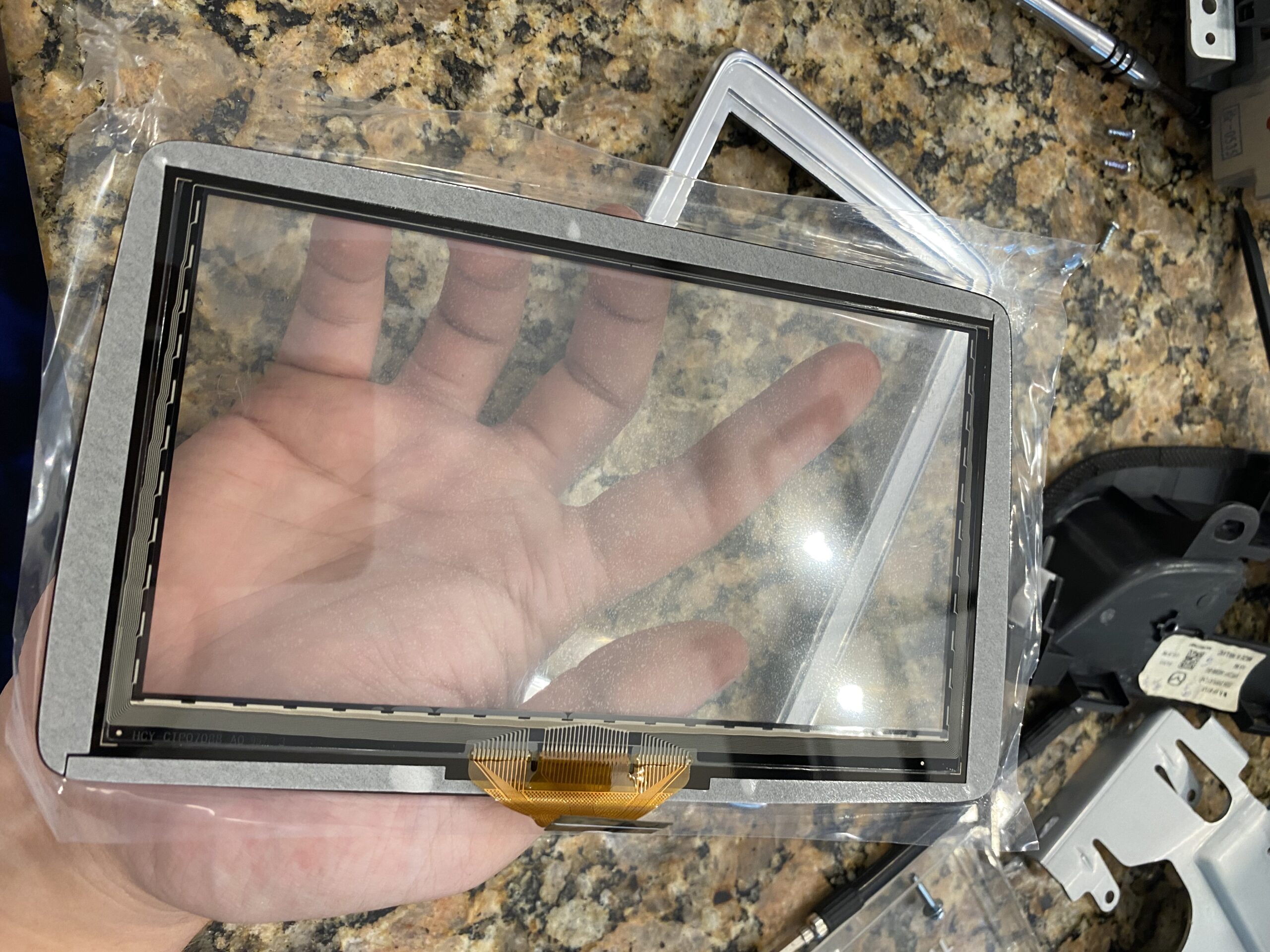
Before ordering parts, verify which touchscreen digitizer your screen uses.
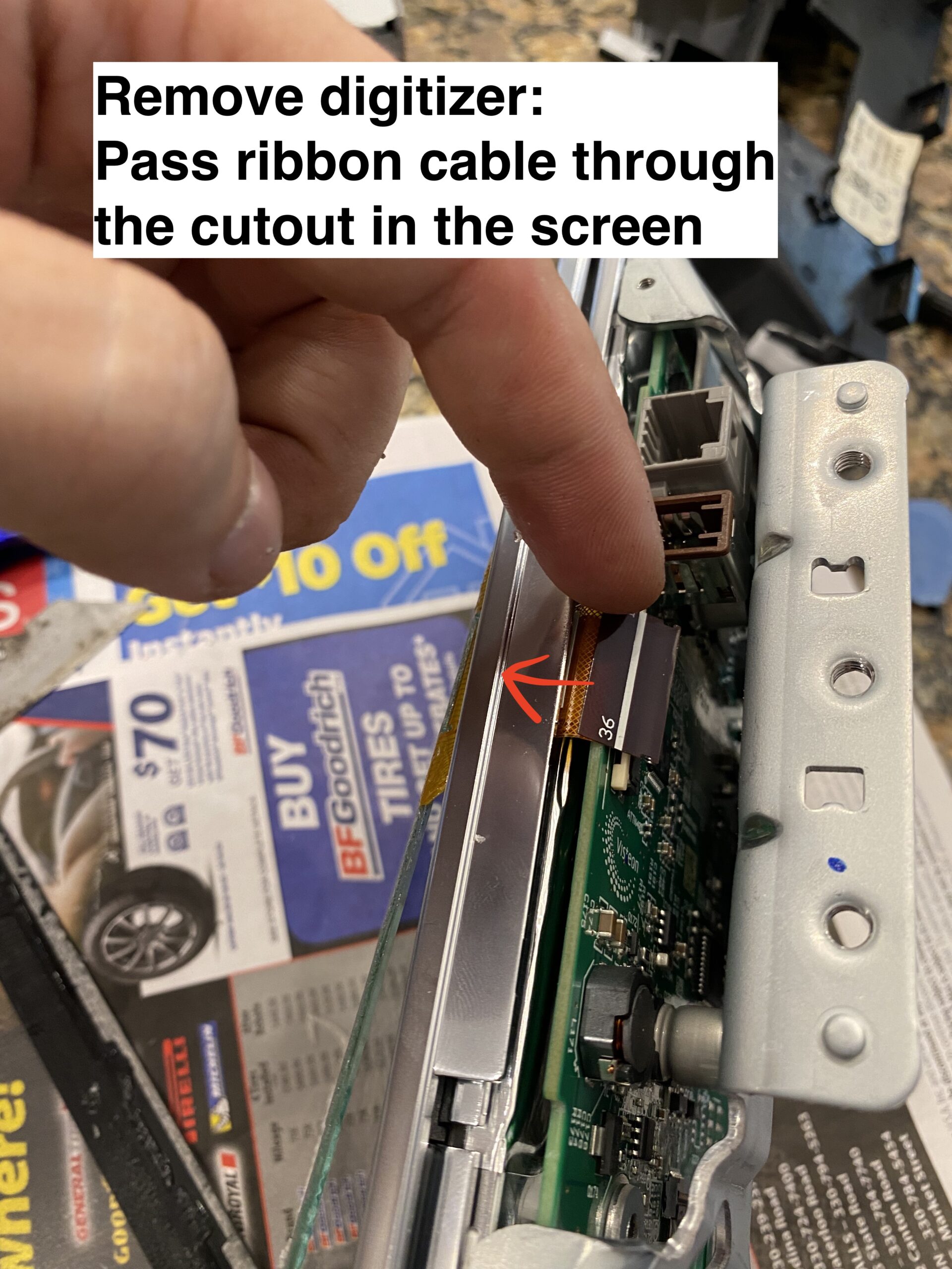
The 36-pin version is typically found on older assemblies, while the 50-pin digitizer is the newer design. Always confirm your connector type before purchasing a replacement.
It is said that 2018+ models with the black bezel trim (instead of chrome) feature the newer 50 pin digitizer. If someone can confirm this, and post a comment, that would be extremely helpful.
Note 2: None of this applies to the ND3 (2024+) This is a completely different screen, and so far no reports of digitizer de-lamination.
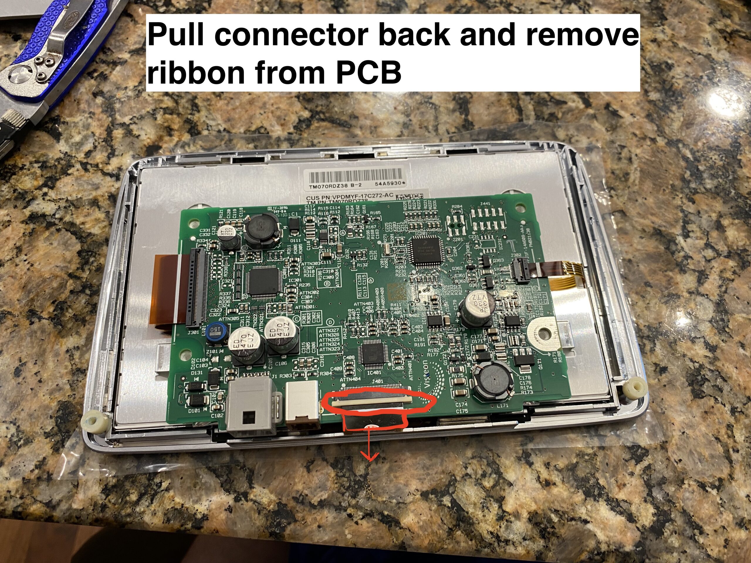
Use caution: parts of this repair require careful handling to avoid damaging the screen PCB or ribbon cables. If you are not comfortable working on delicate electronics, this may not be the right DIY project for you.
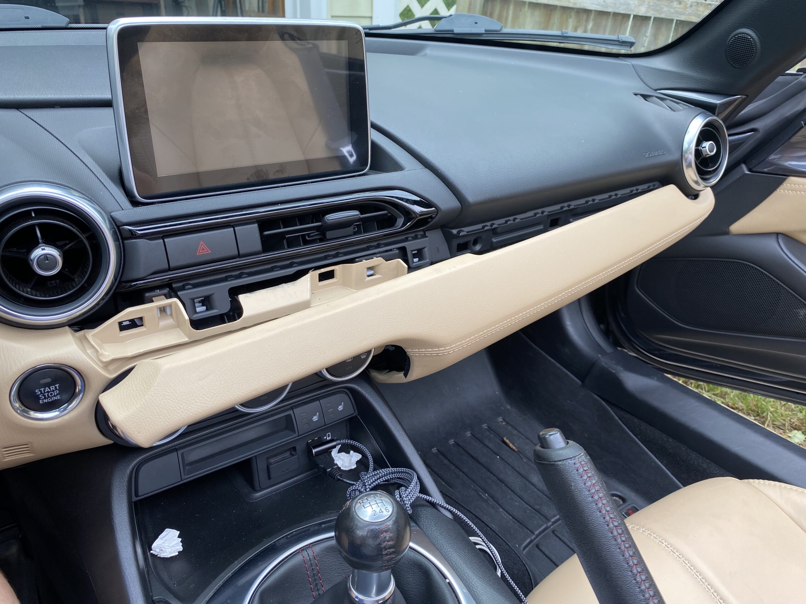
These photos were taken during reassembly after the screen was repaired, so some images may show the unit going back together rather than coming apart.
If this guide helps you, consider using the affiliate links below to purchase the needed parts.
Buy 36 pin replacement touchscreen on eBay (Affiliate Link)
Buy 36 pin replacement touchscreen on Amazon (Affiliate Link)
Buy 50 pin replacement touchscreen on eBay (Affiliate Link)
Buy 50 pin replacement touchscreen on Amazon (Affiliate Link)
Disclosure: When you click certain links on this site and make a purchase, this site may earn a commission through affiliate programs, including the eBay Partner Network and Amazon affiliate links.
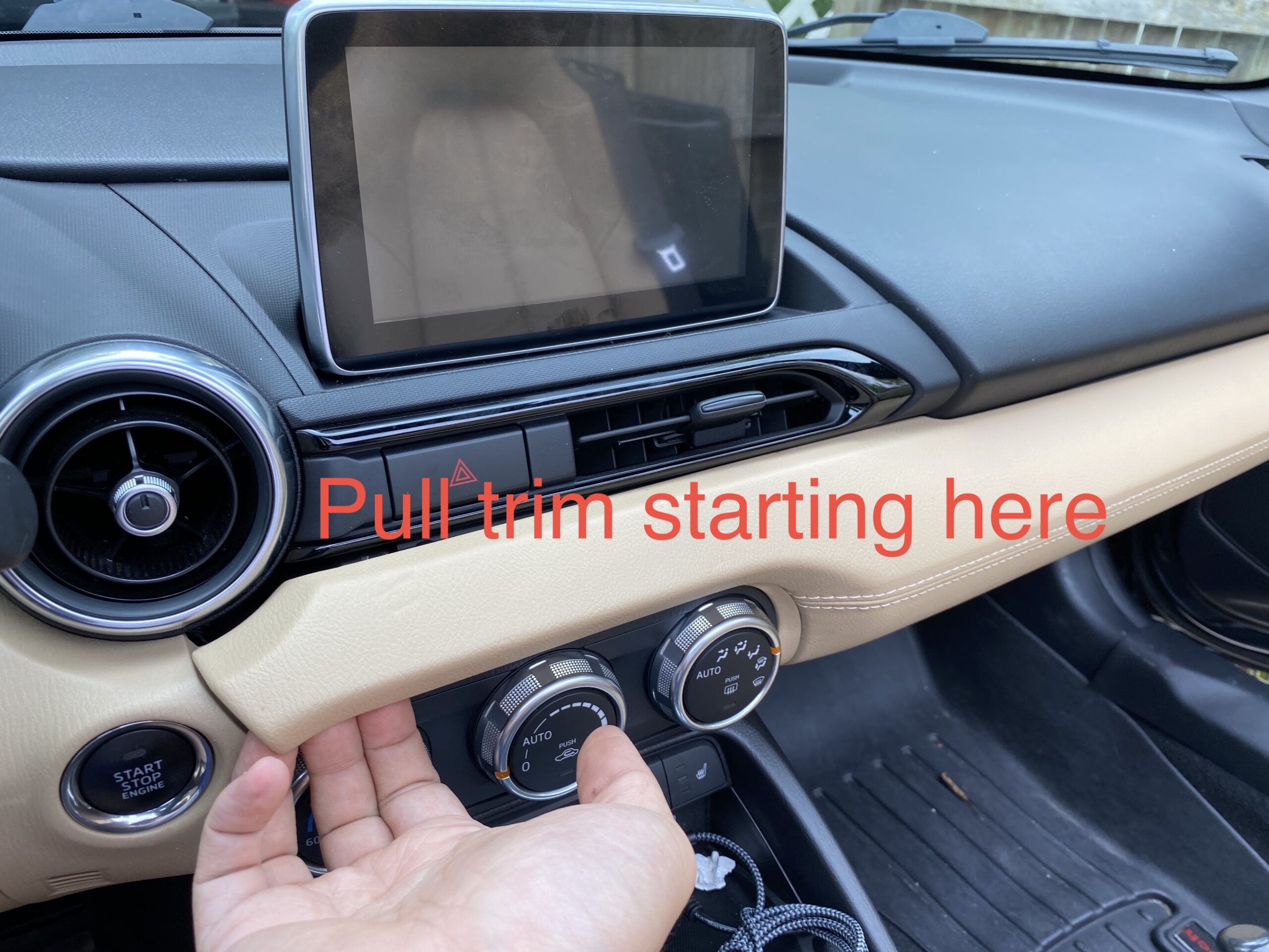
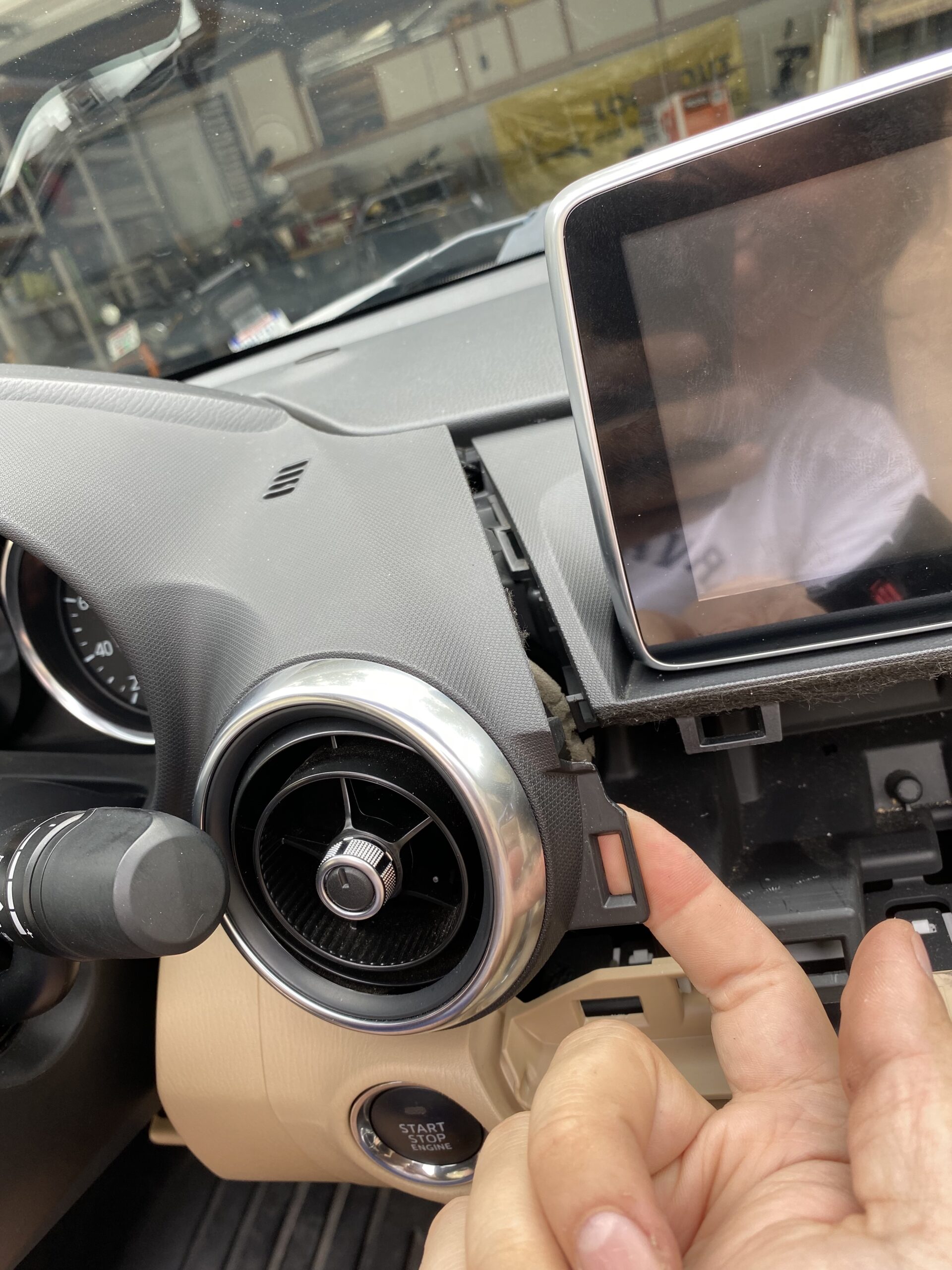
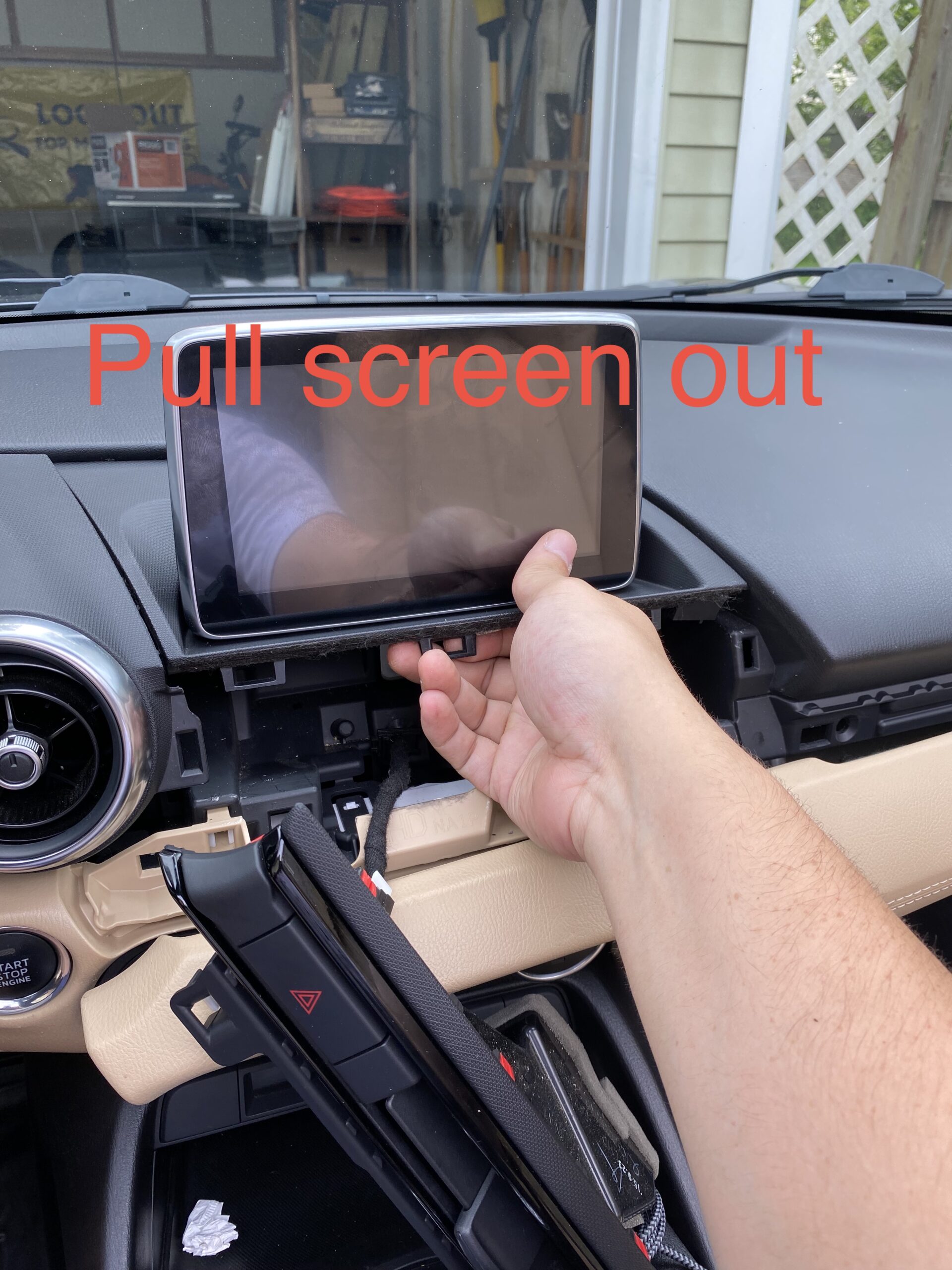
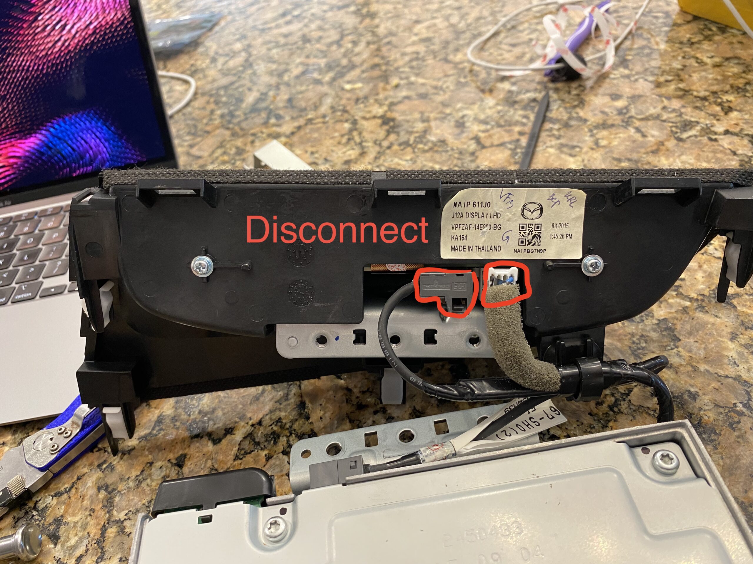
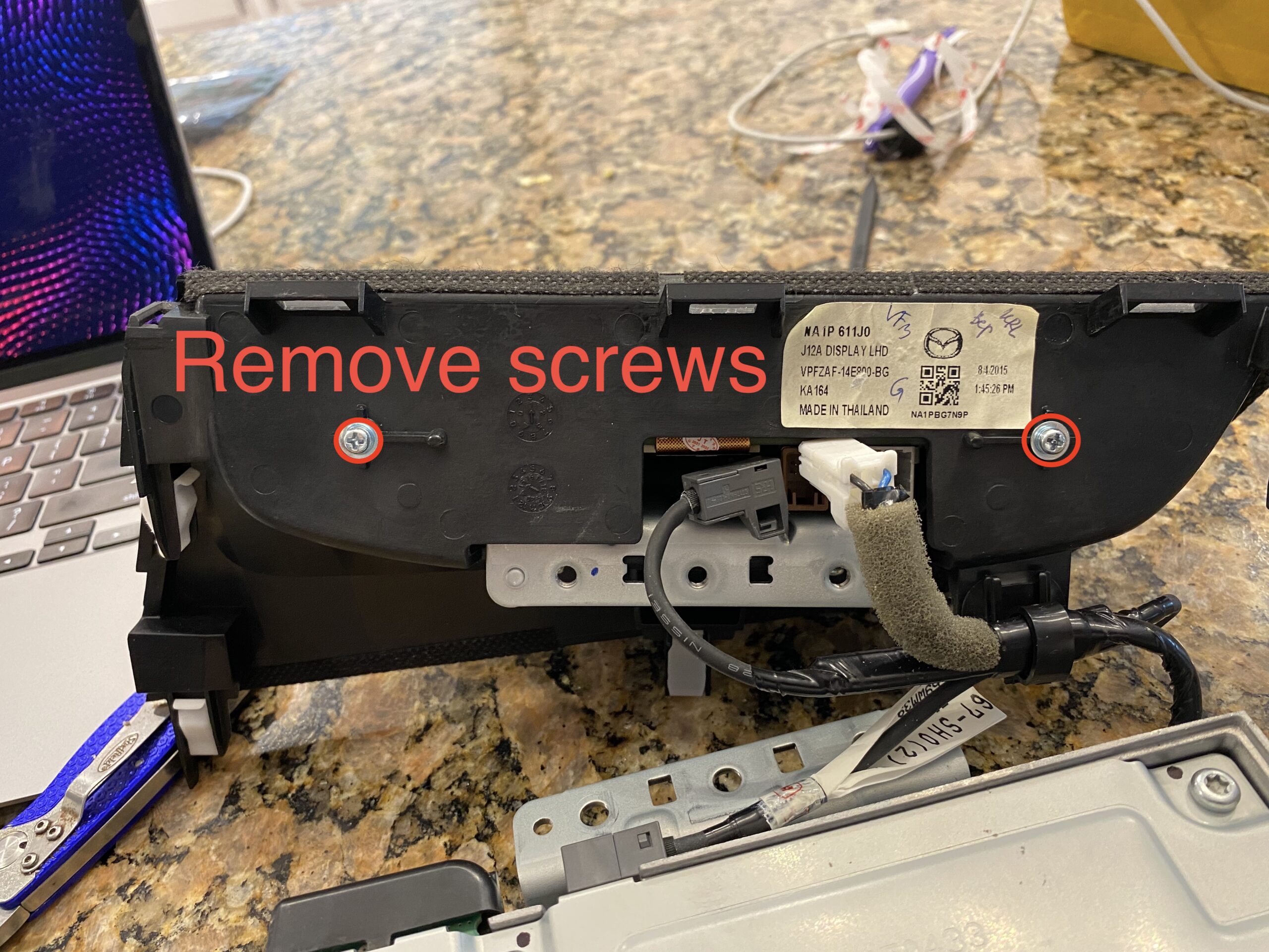
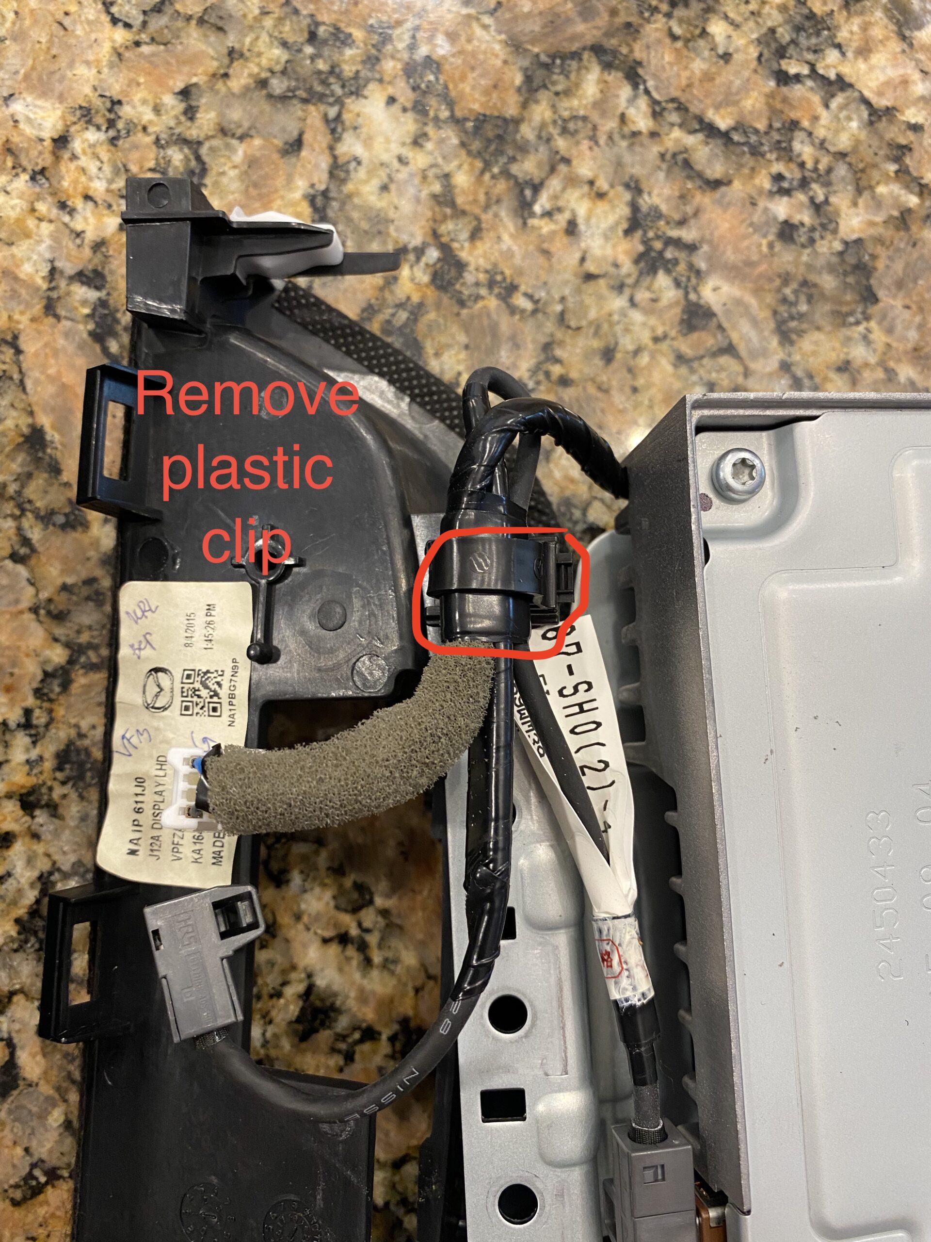
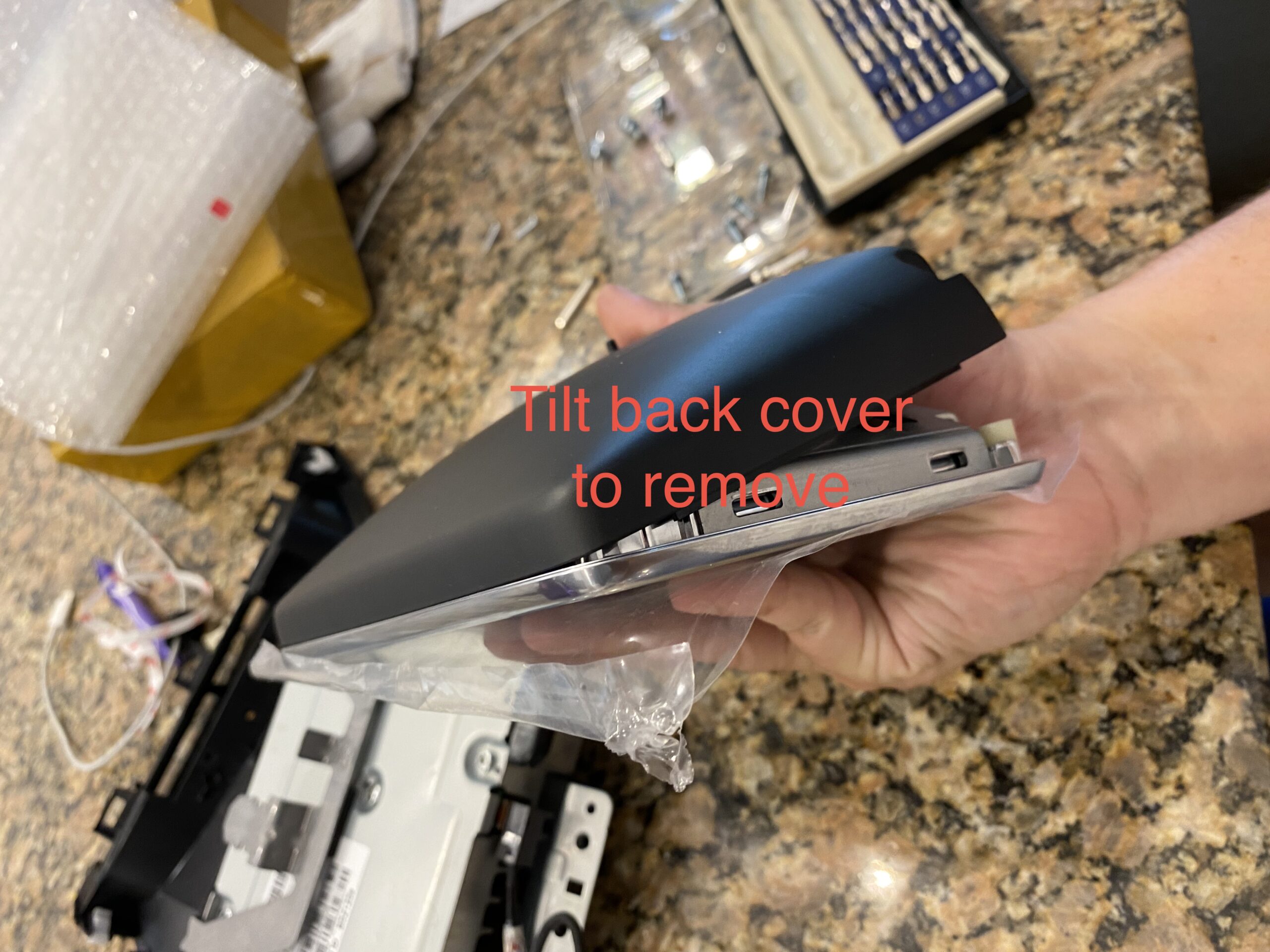
Follow the repair in stages instead of scrolling through one long wall of photos.
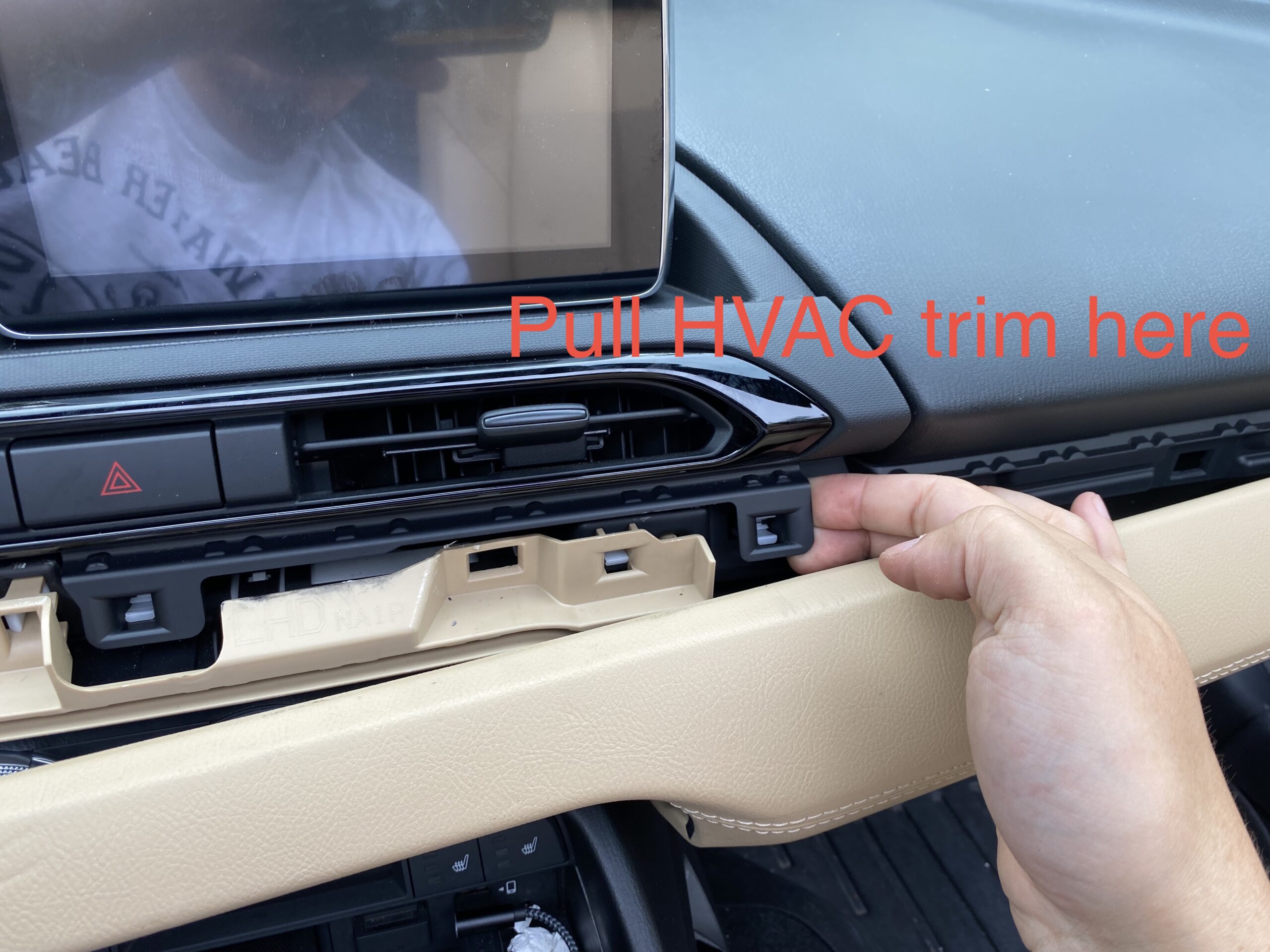
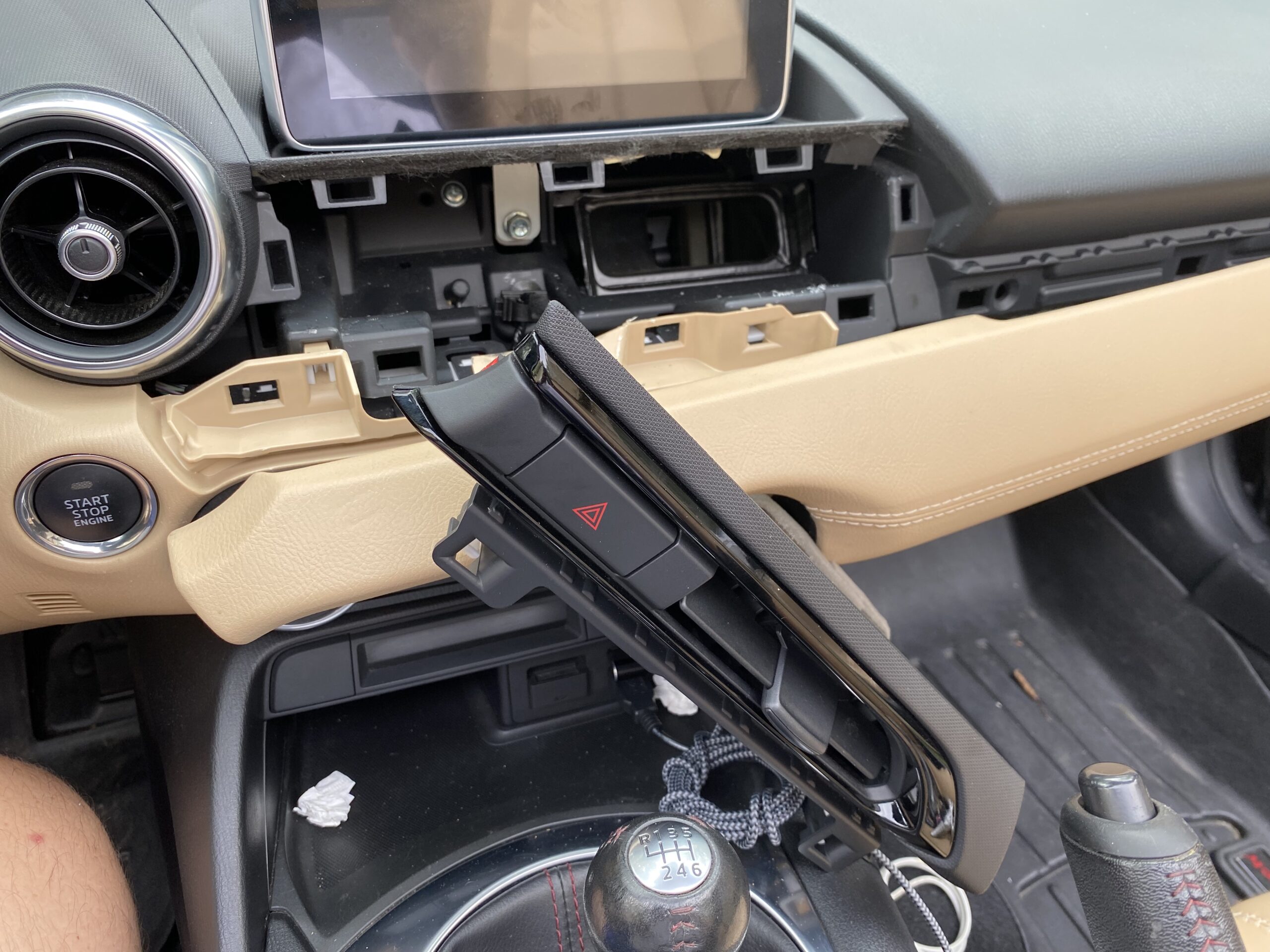
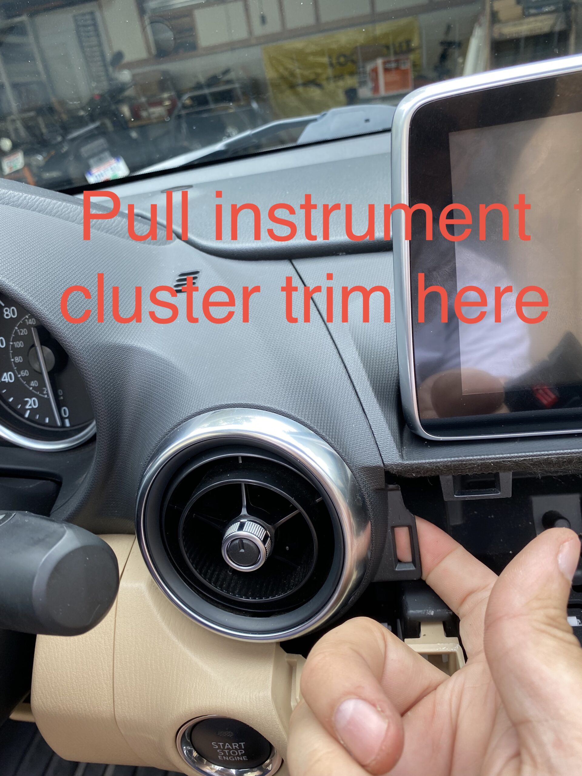
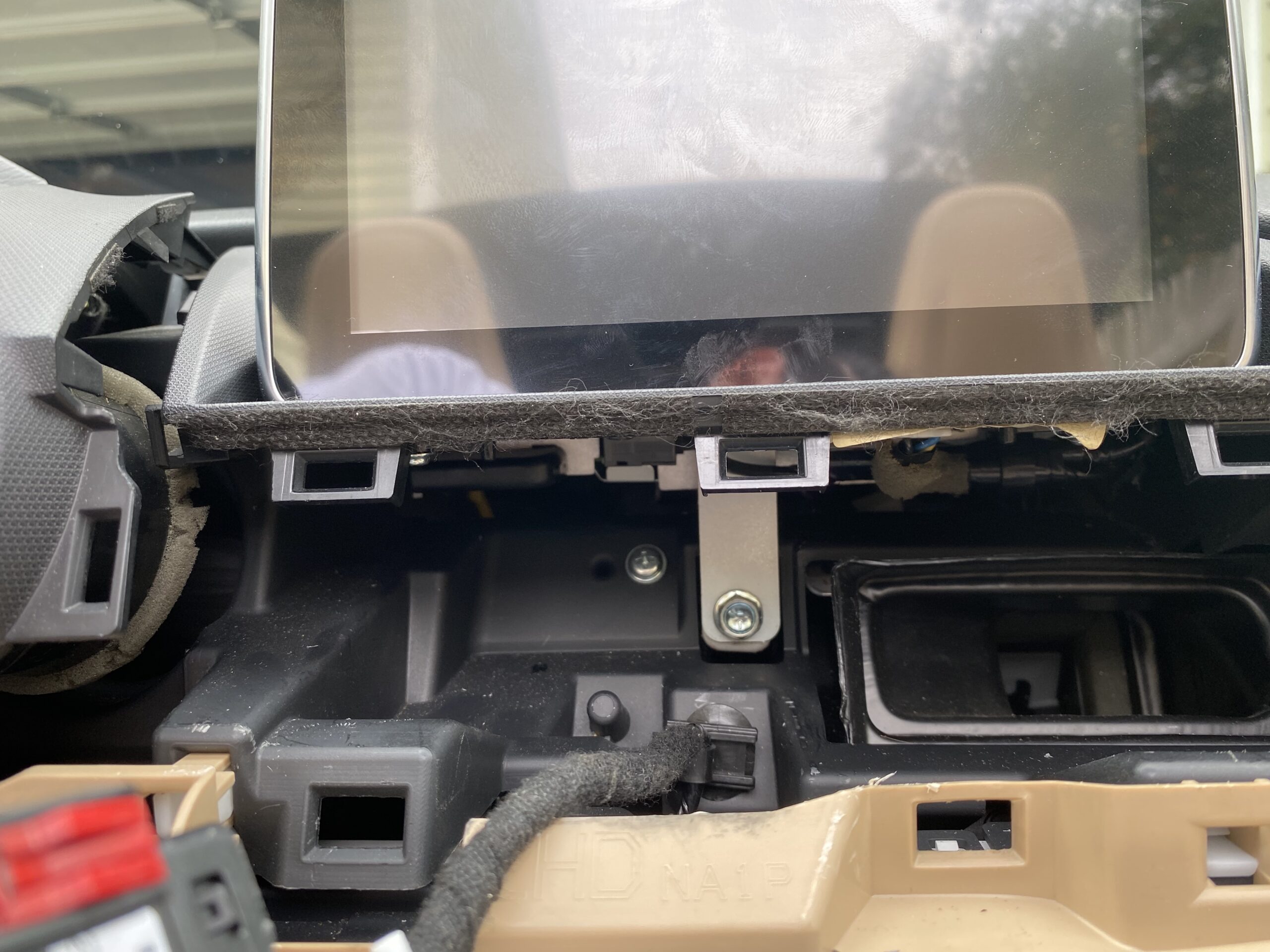
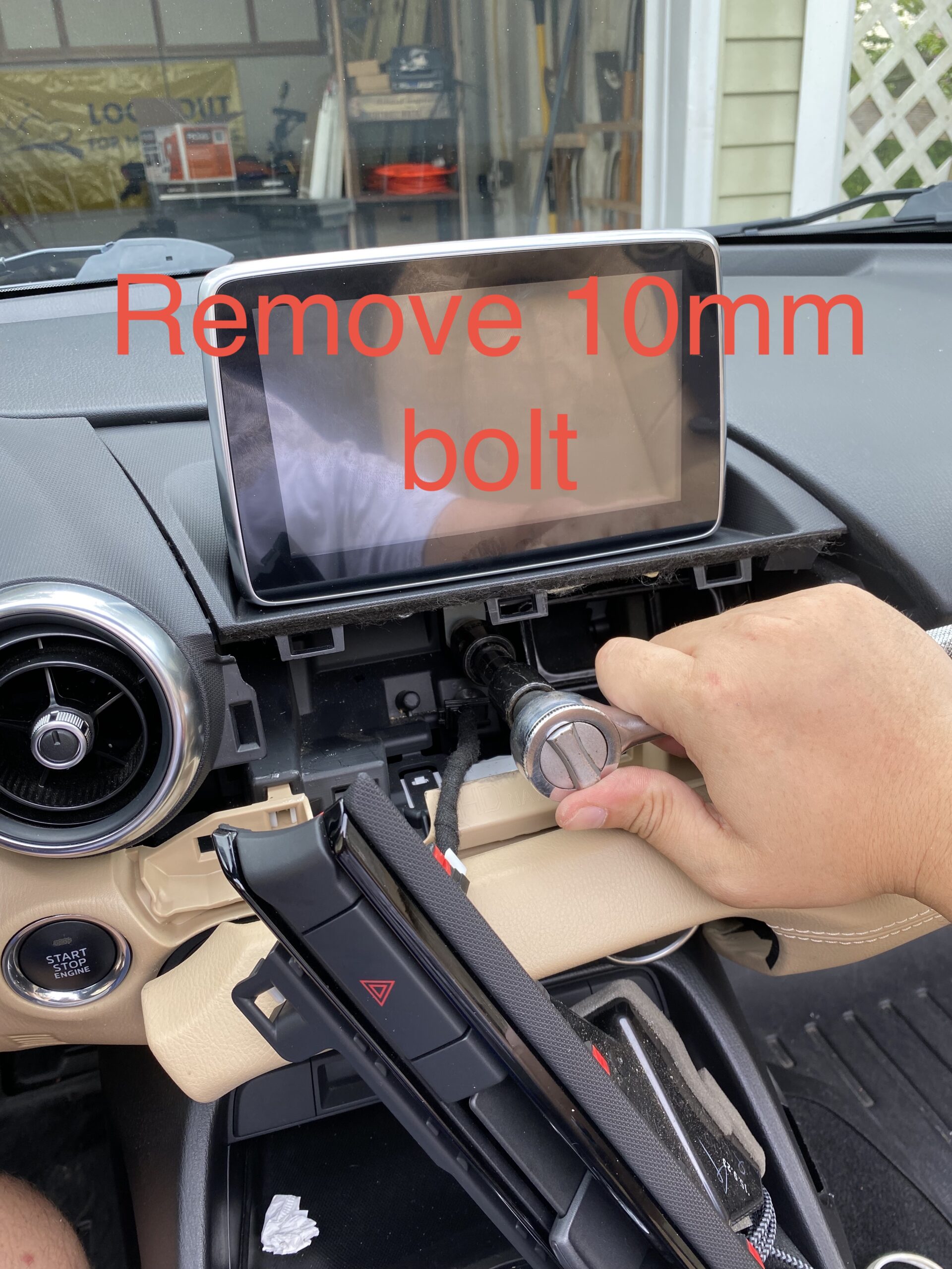
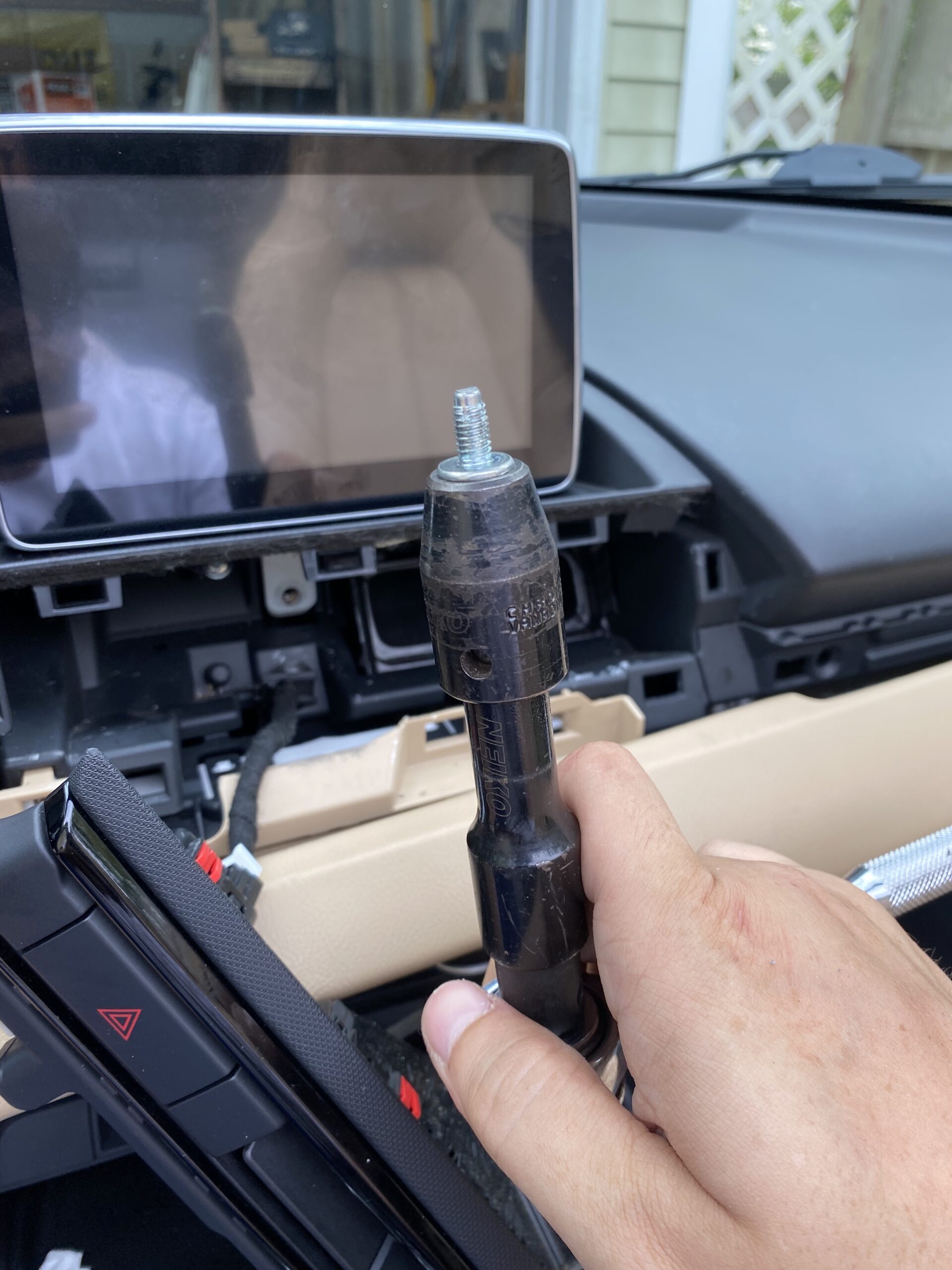
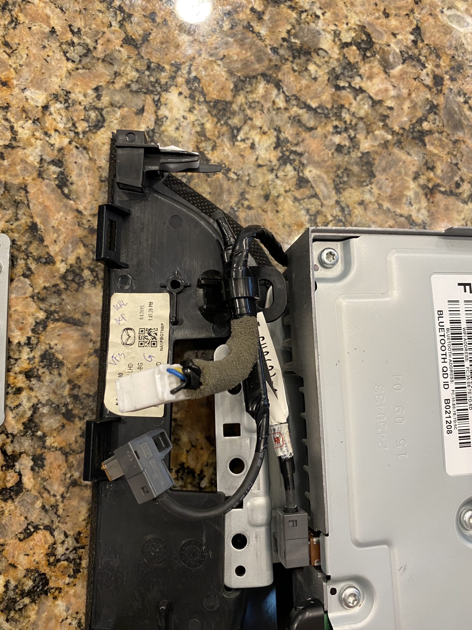
Start by removing the trim pieces and screen assembly carefully. Keep track of screws and clips as you go.
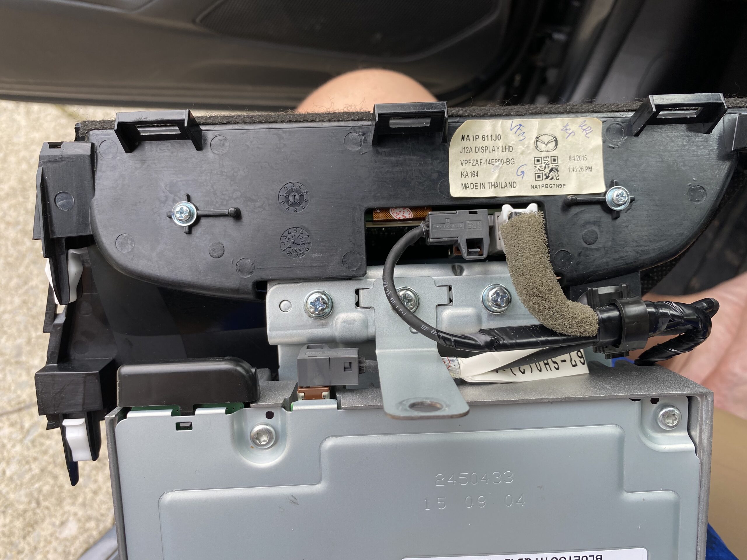
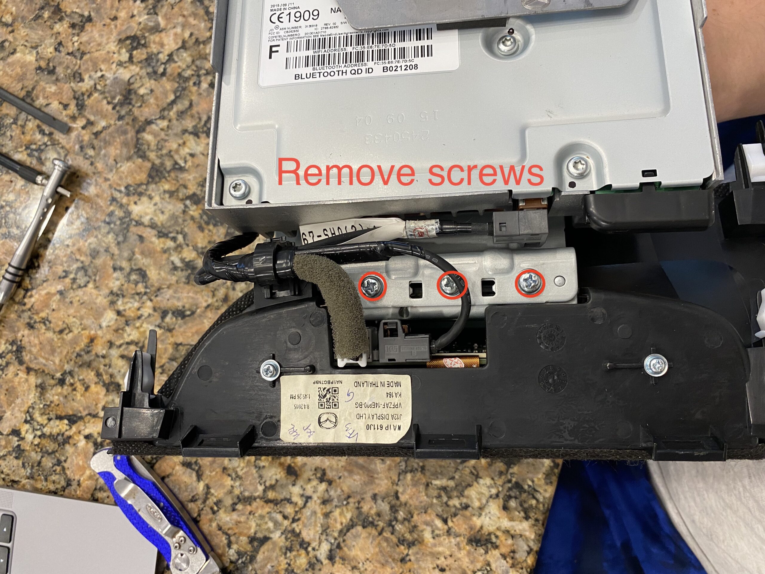
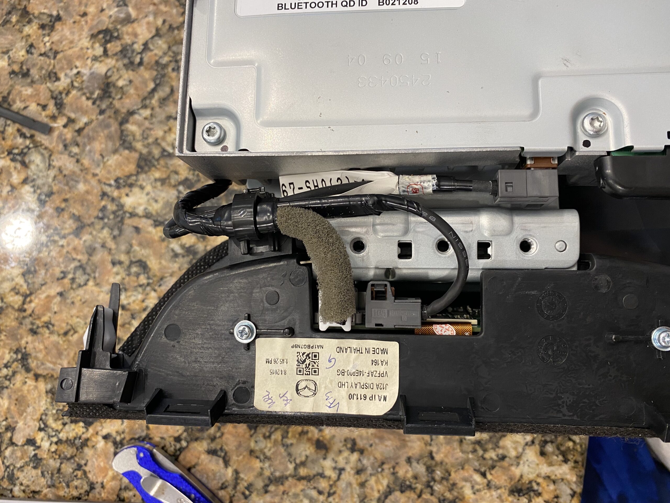
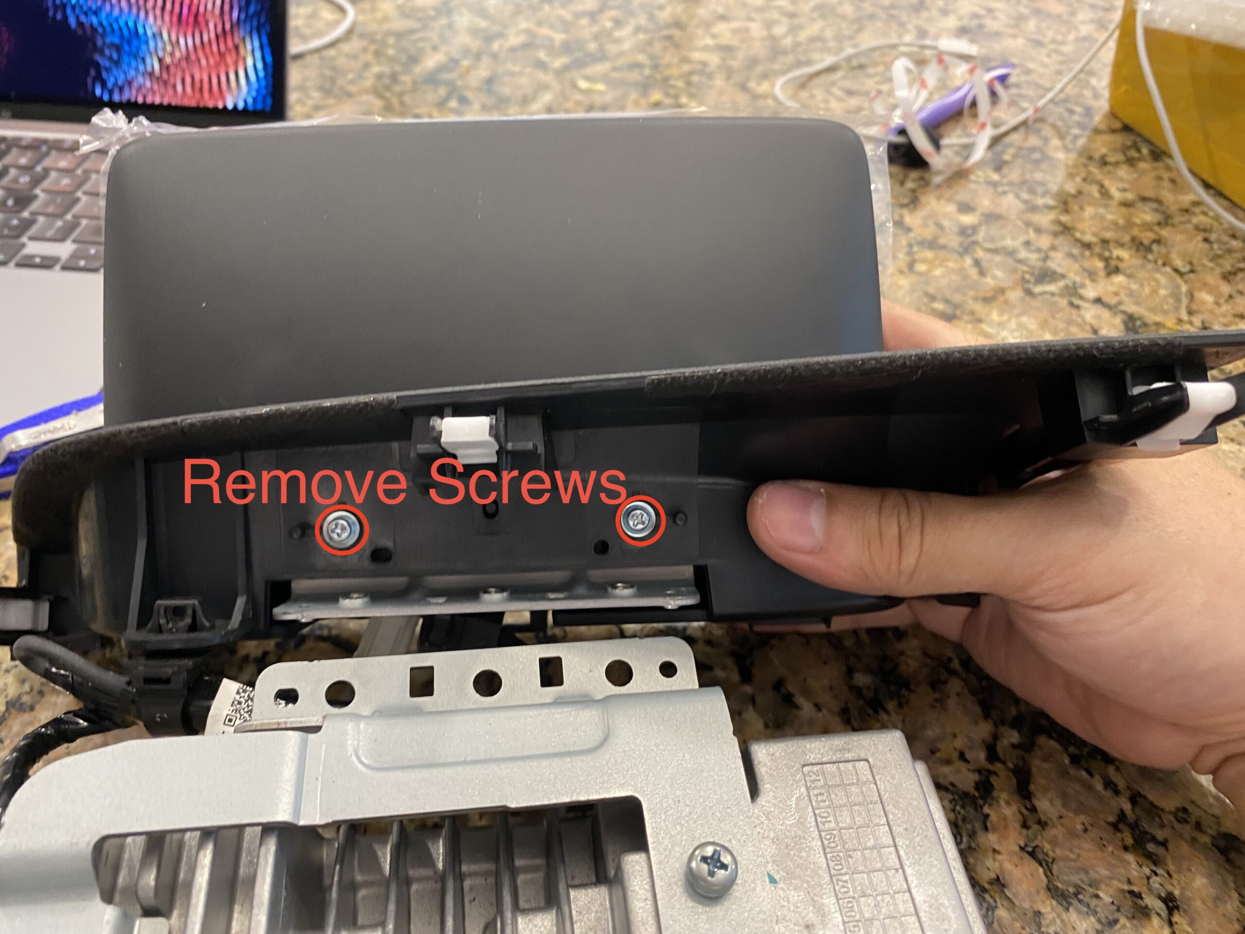
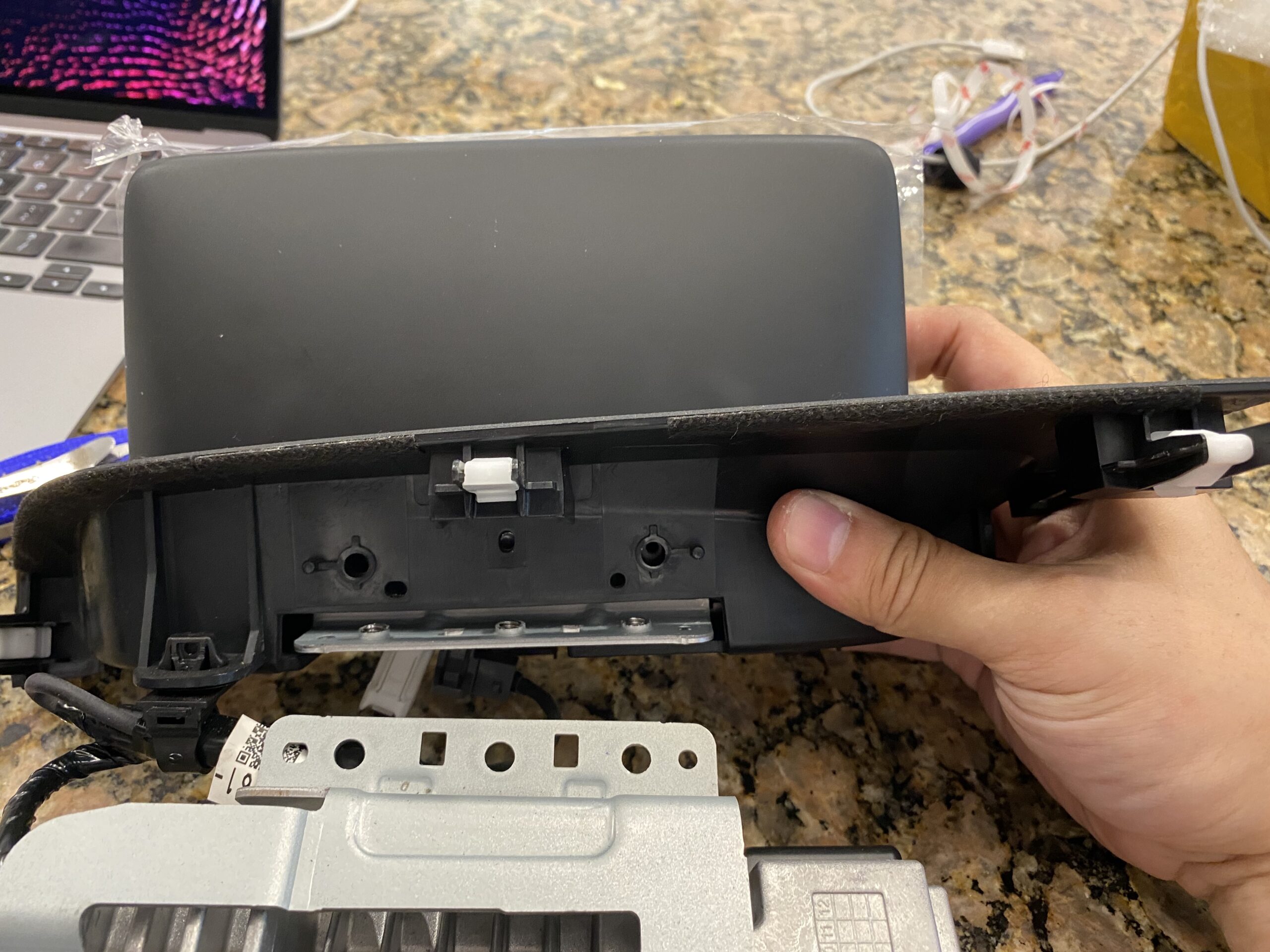
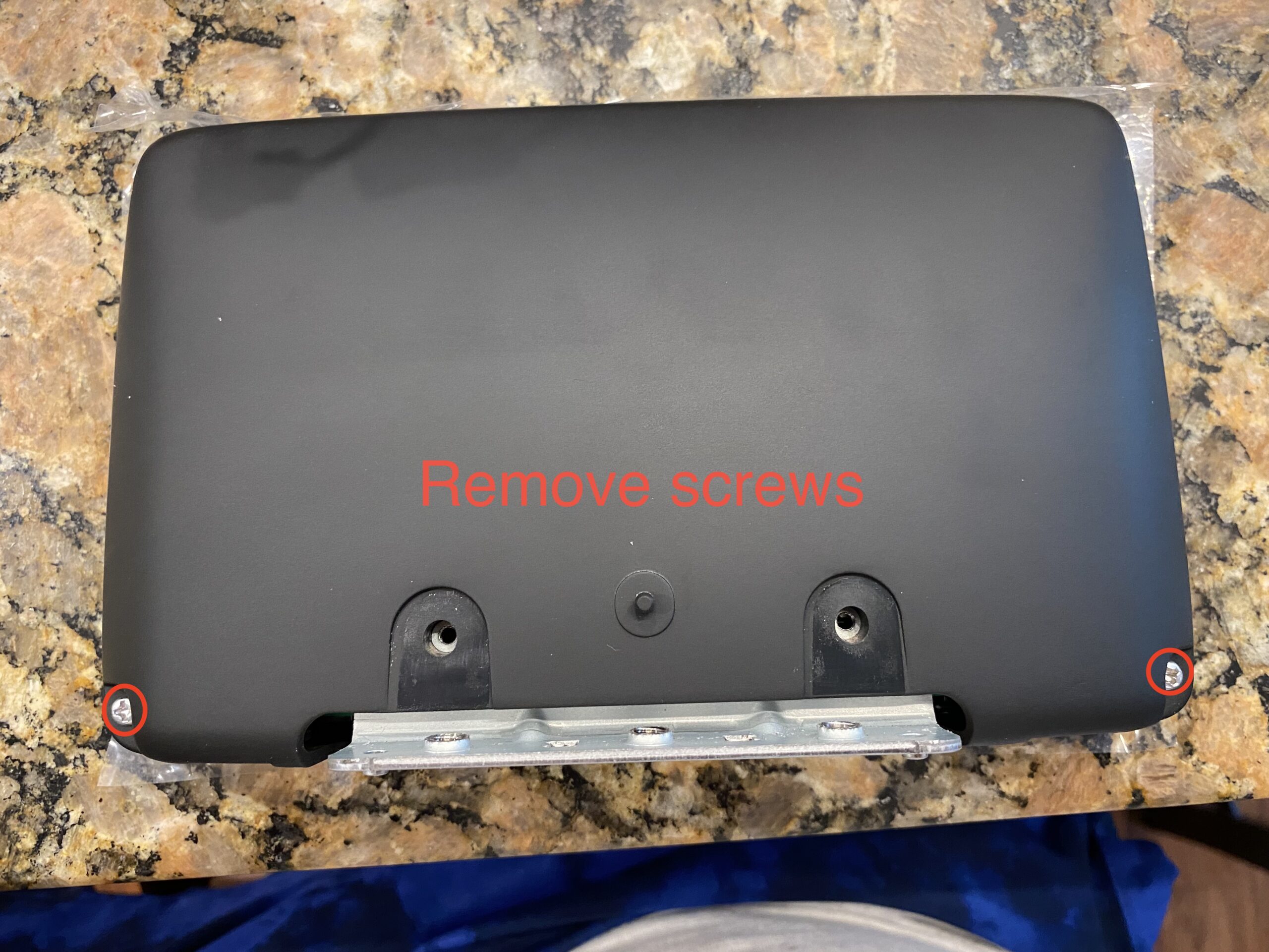
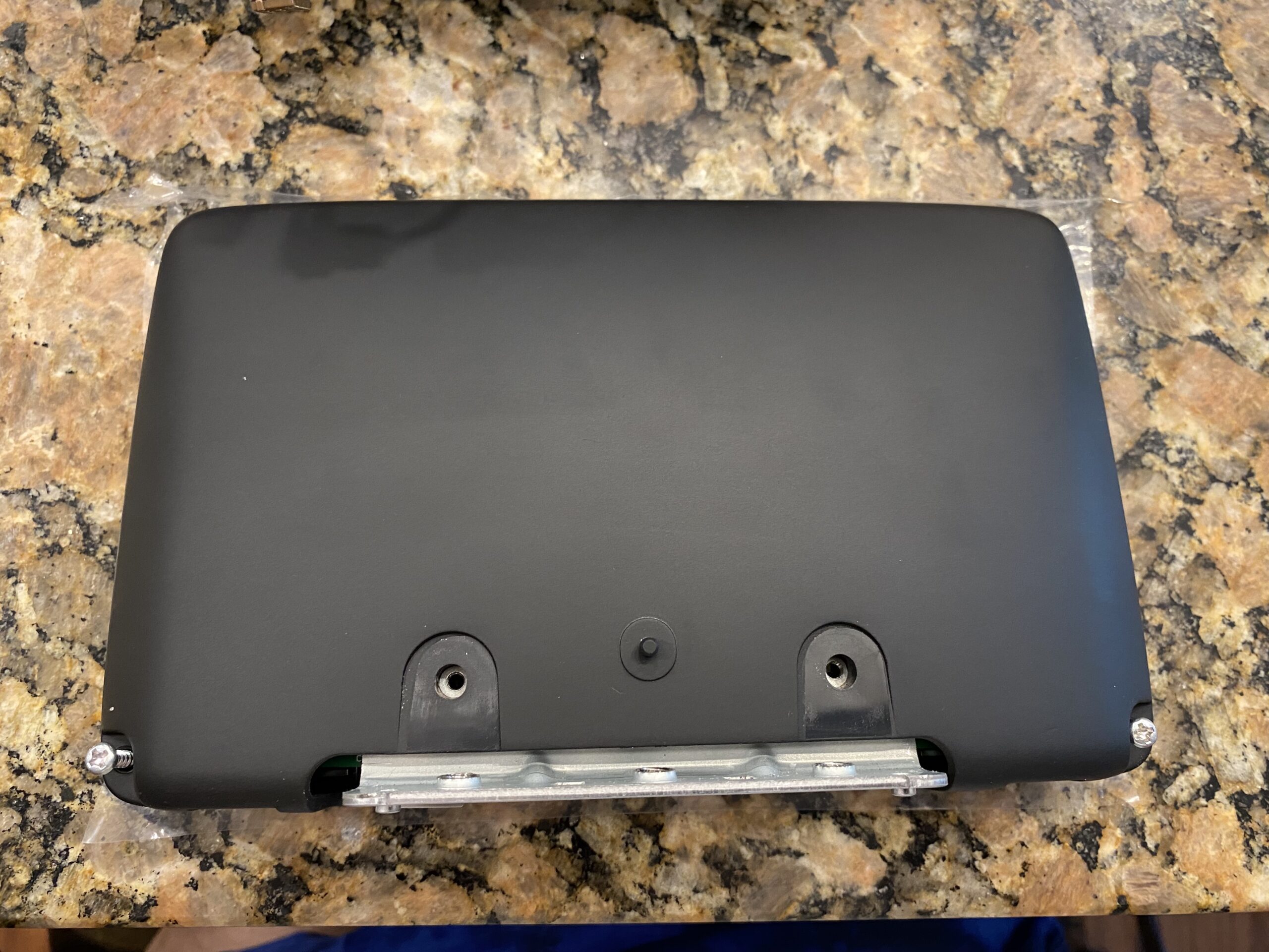
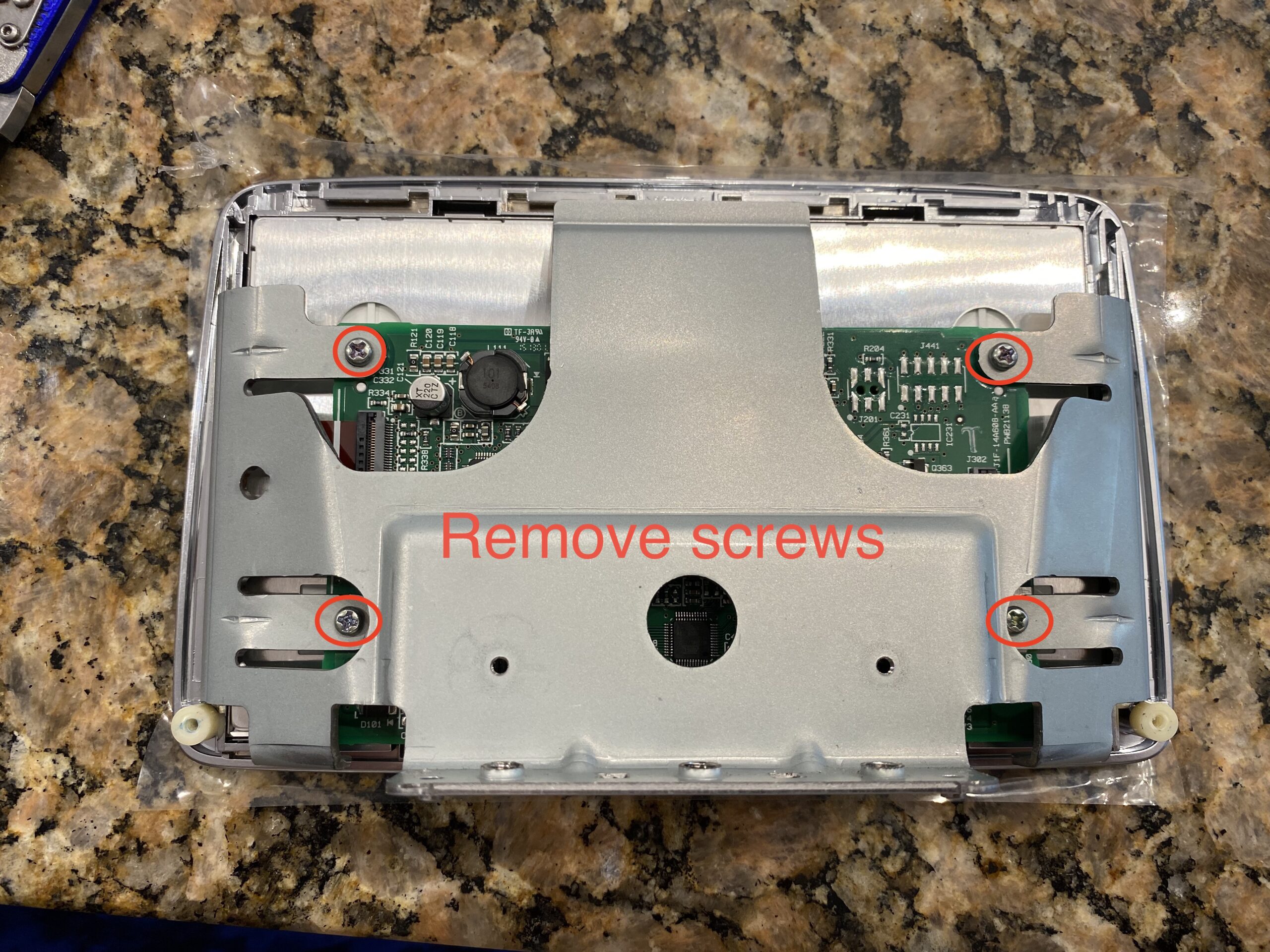
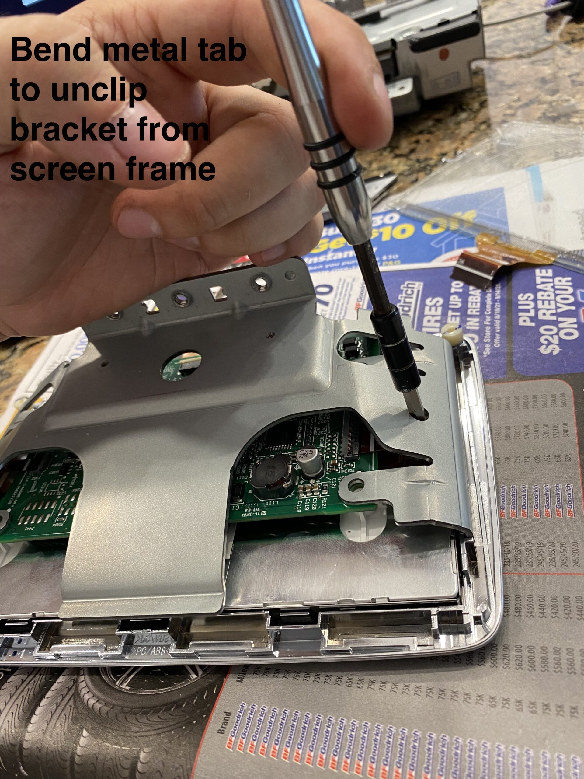
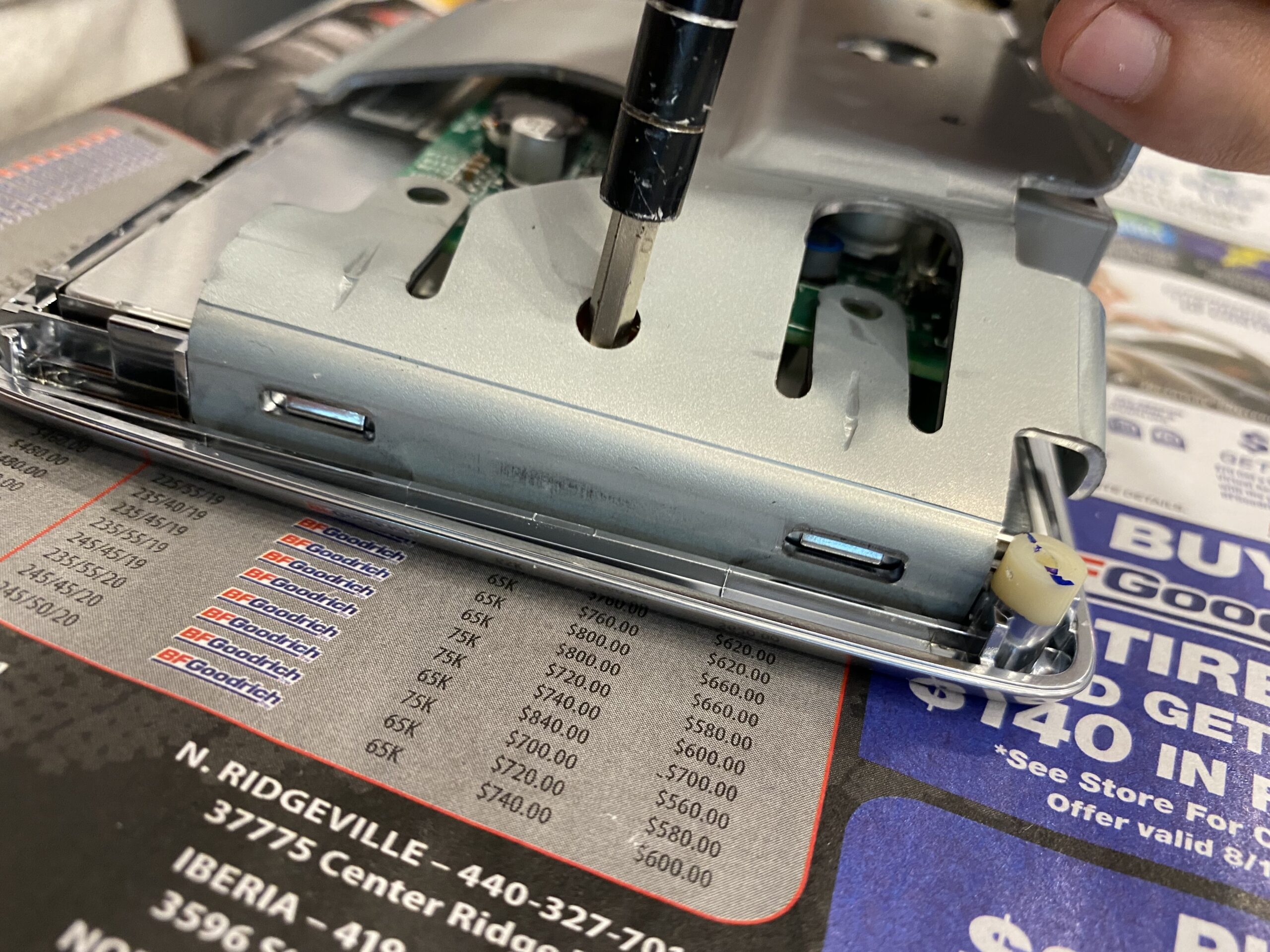
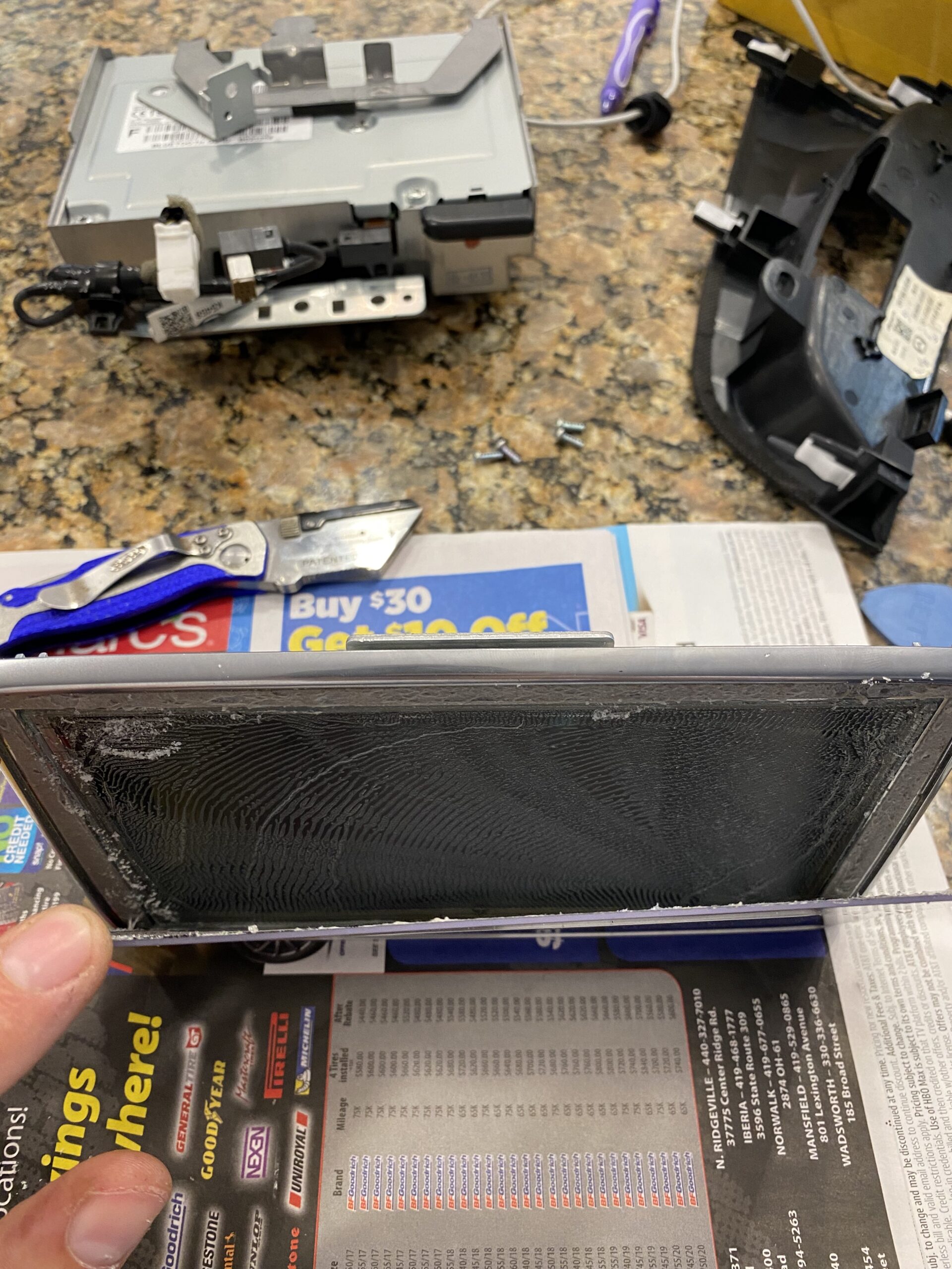
Separate the housing and expose the internal components carefully, avoiding stress on any ribbon cables.
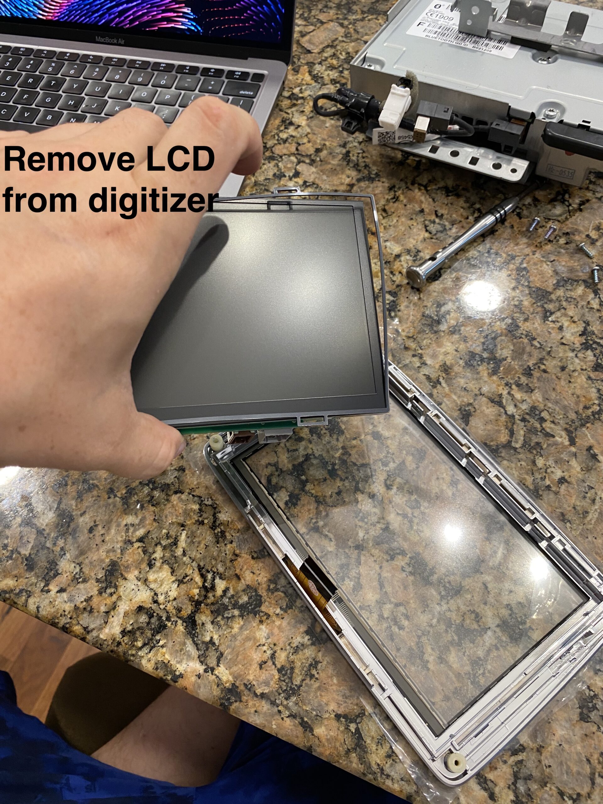
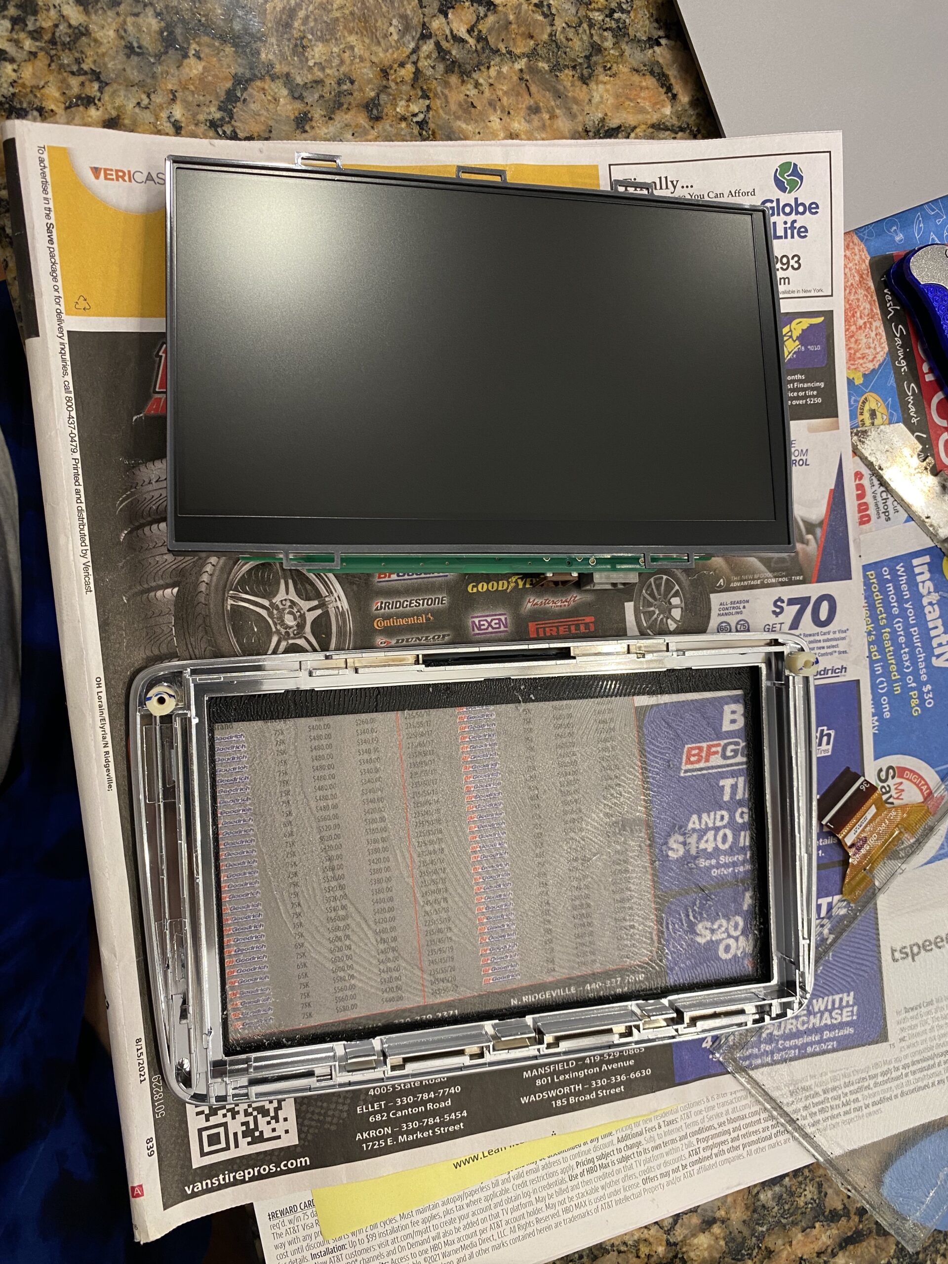
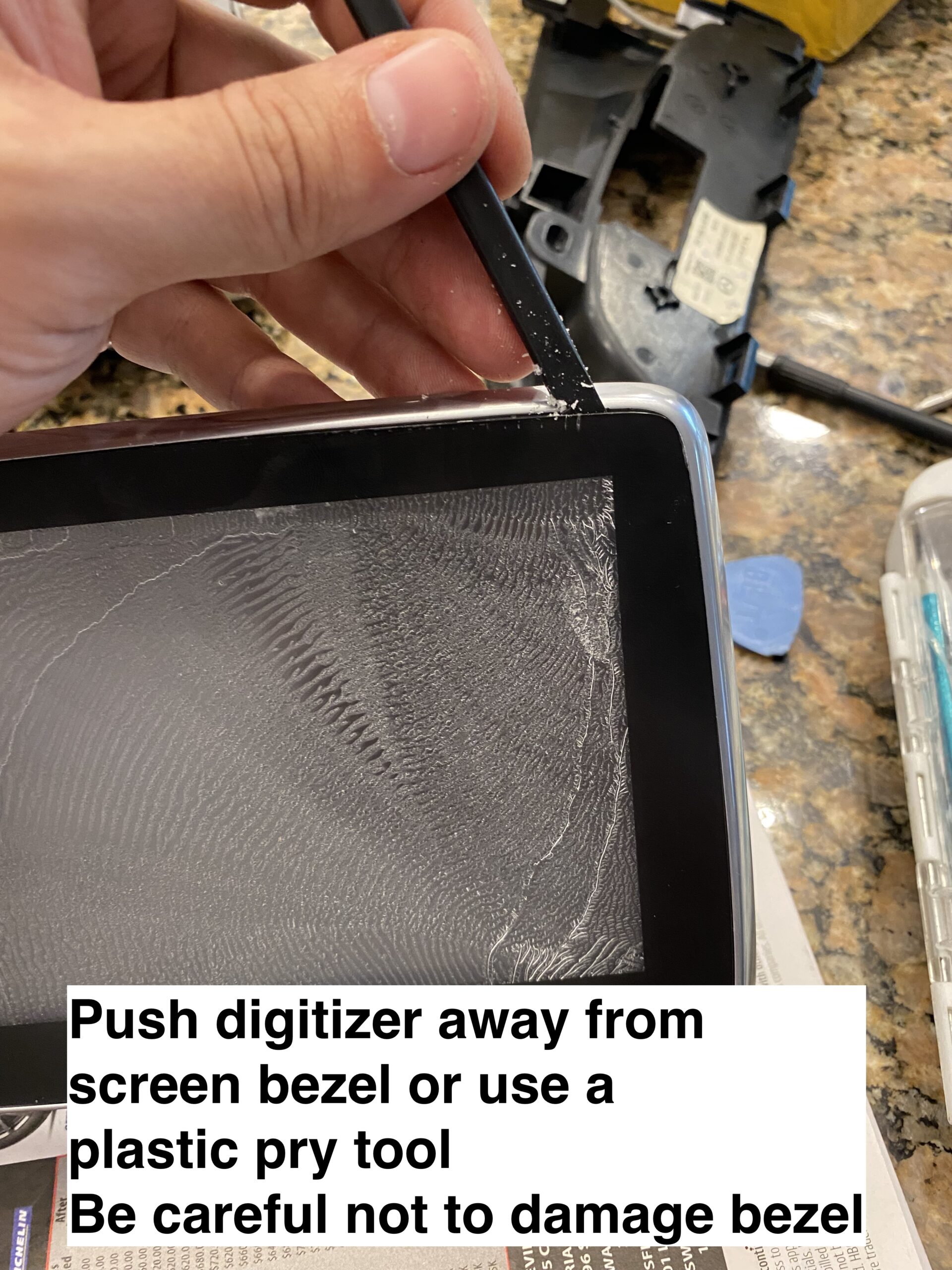
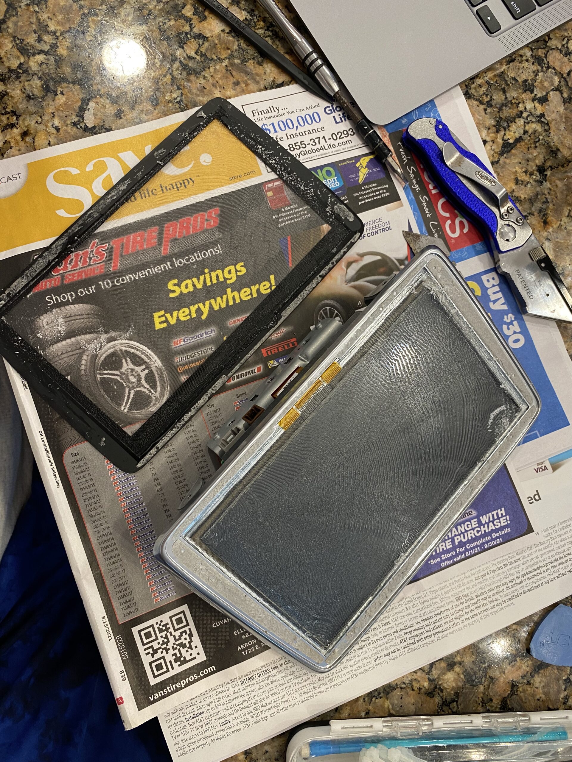
Work slowly when separating the old digitizer from the display assembly. Use heat carefully if needed to soften the adhesive.
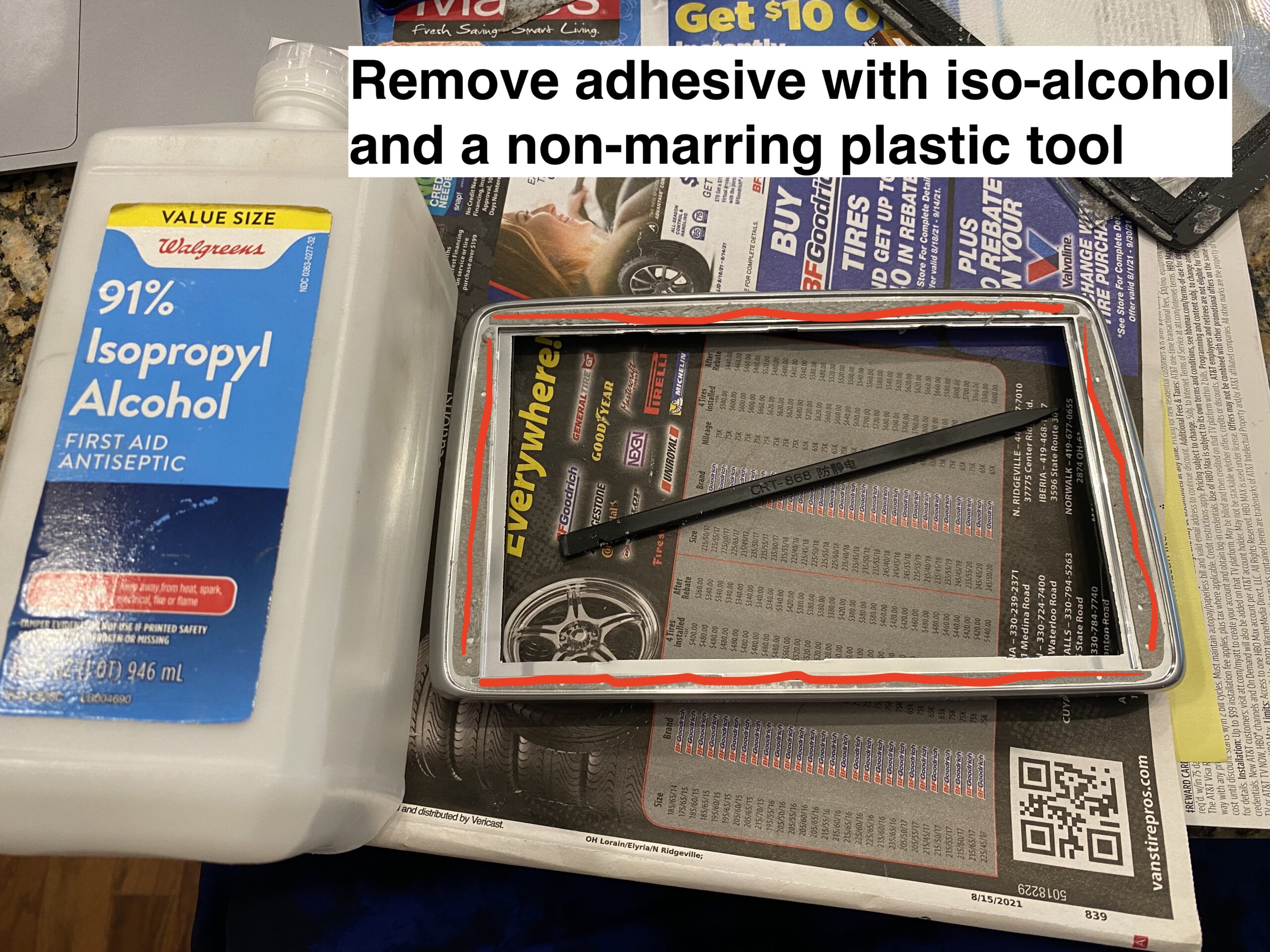
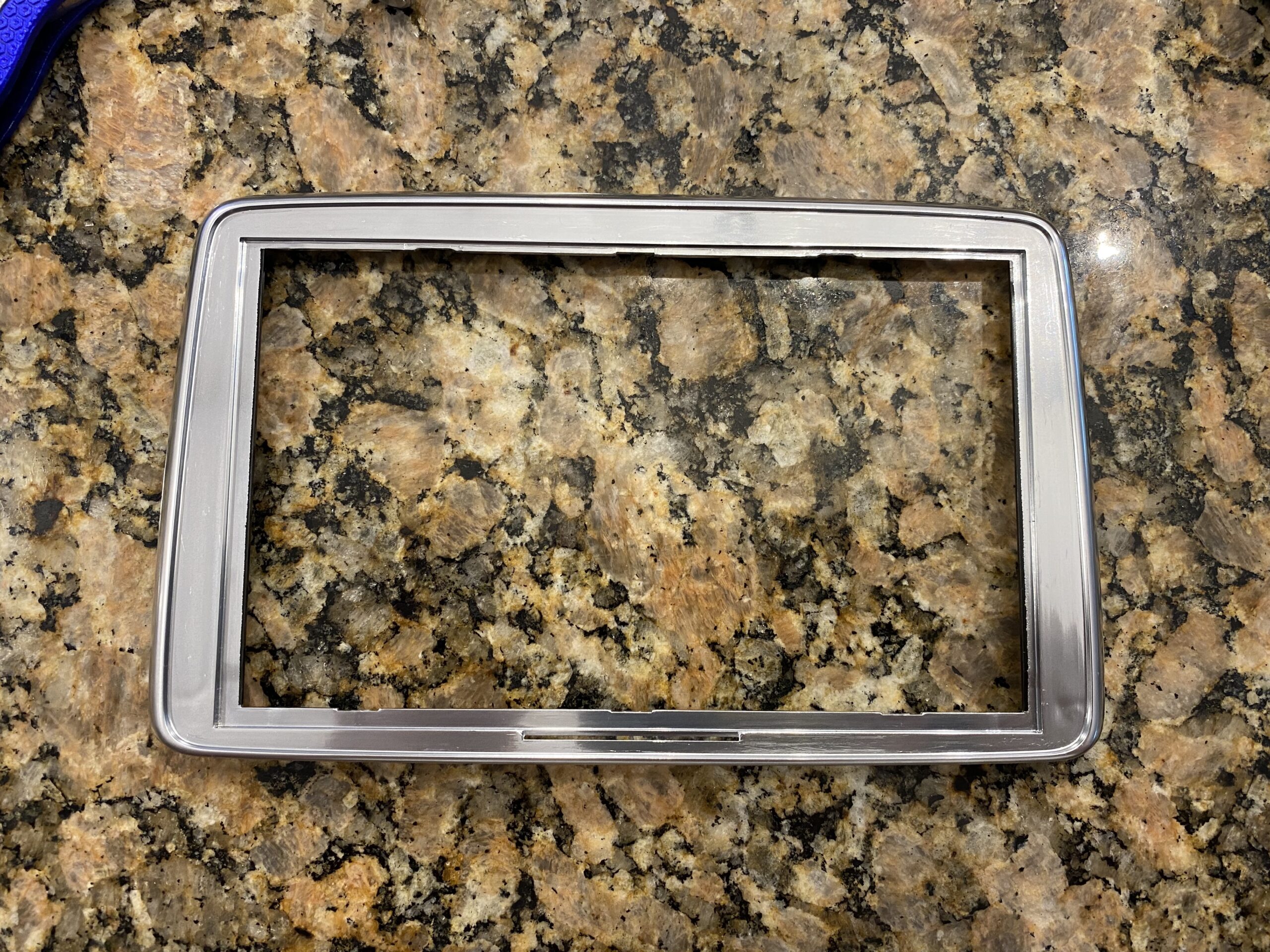
Remove all remaining adhesive and debris so the new digitizer can sit flat and bond properly.
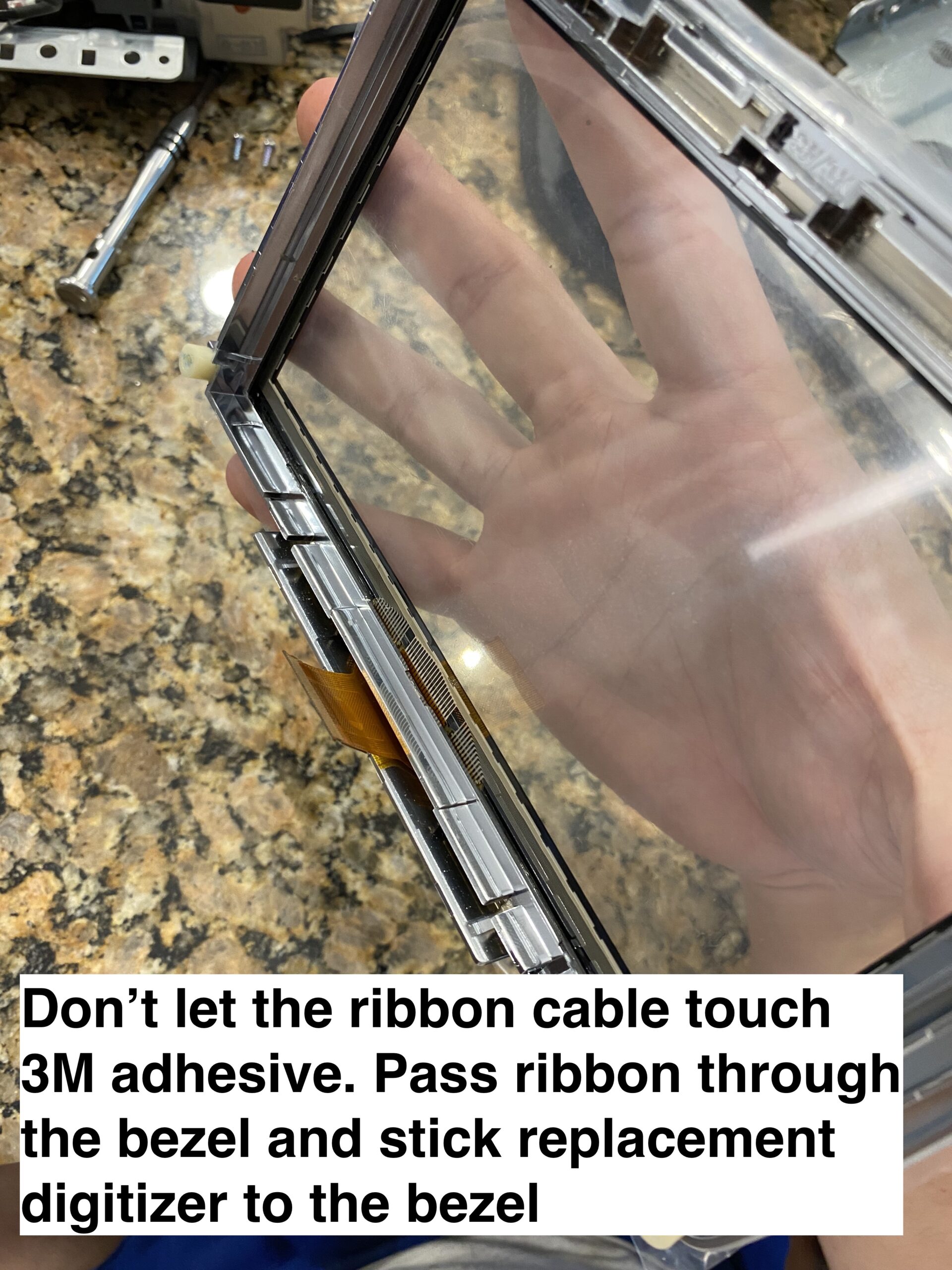
Align the new digitizer carefully, route the ribbon correctly, and make sure the assembly sits flat before reassembly.
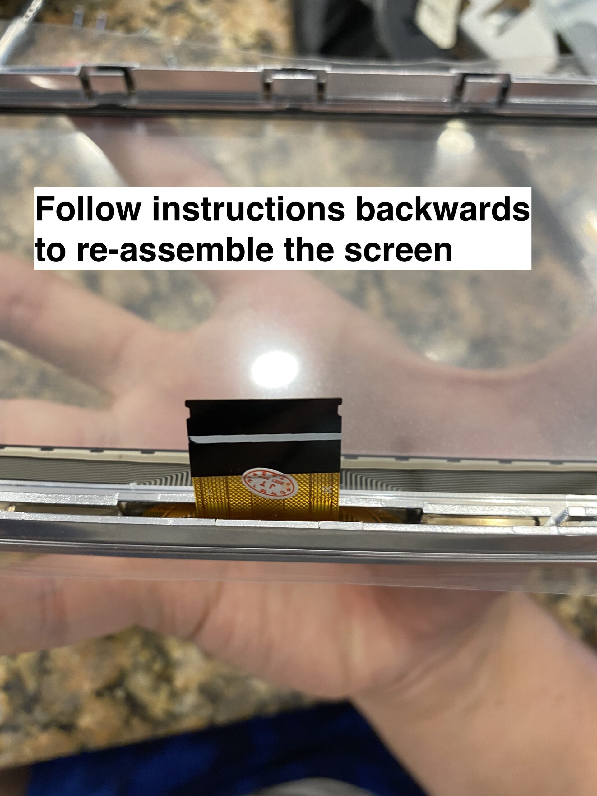
Reconnect everything, test touch response before fully buttoning it up, and then reinstall the trim pieces.
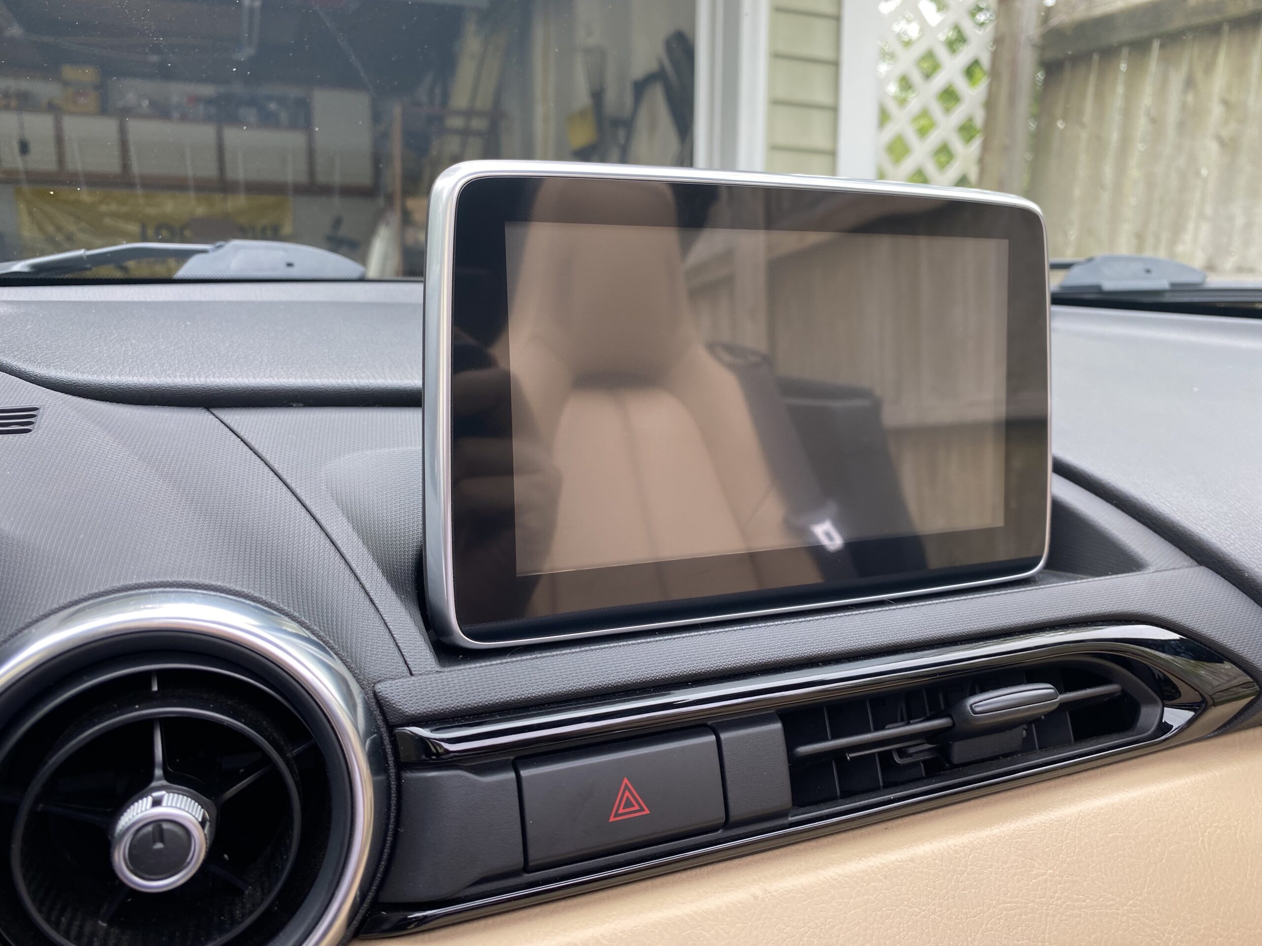
If your Mazda Connect screen is cracked or suffering from ghost touch issues, replacing only the digitizer can save a significant amount of money compared to replacing the full infotainment unit.
The most important step before ordering is confirming whether your screen uses the older 36-pin digitizer or the newer 50-pin digitizer.
This guide will quickly give you very important information you need on provisioning VVX phones with FreePBX
When a phone is factory reset, it will get a DHCP lease.
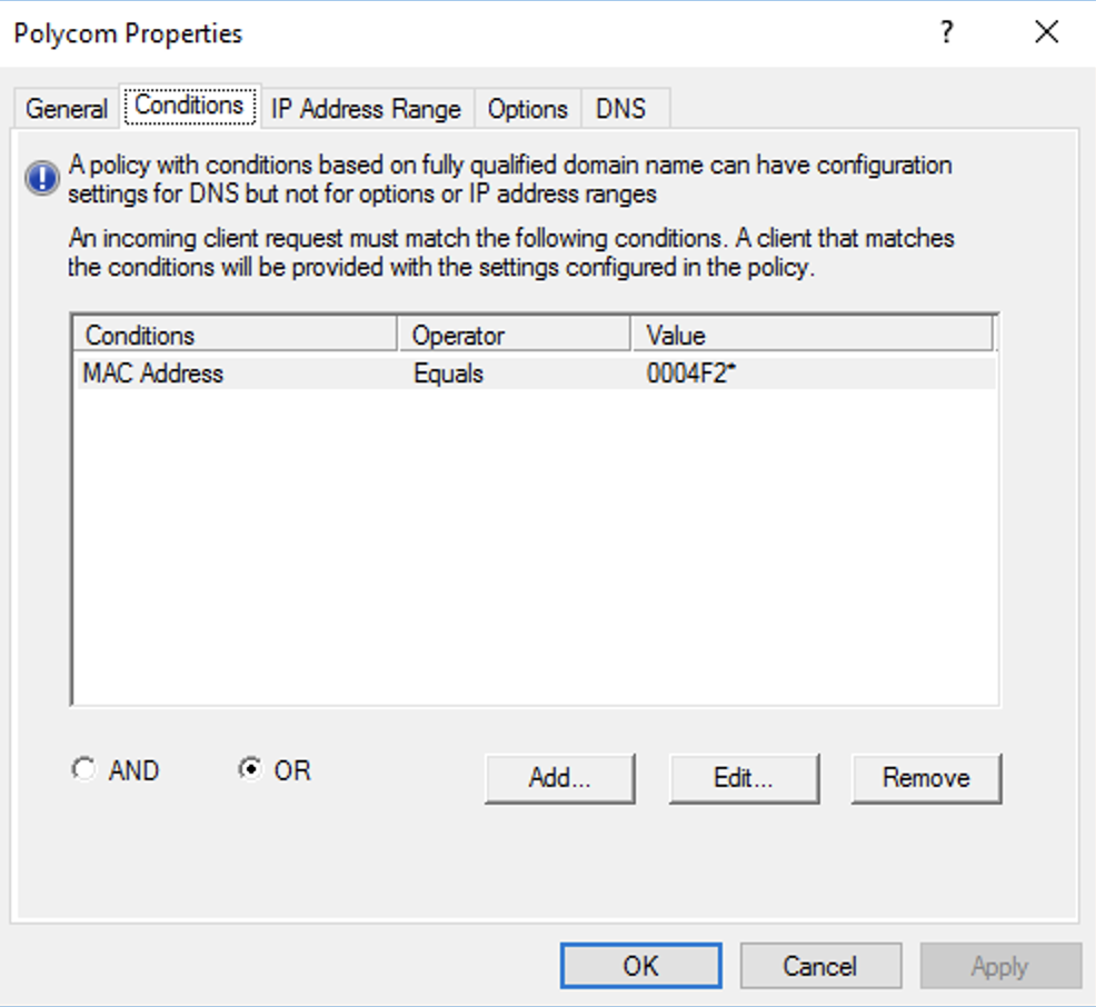
Polycom VVX phones have a mac address starting with 0004F2. You can create a policy in Windows DHCP server to allocate specific IPs to the phones
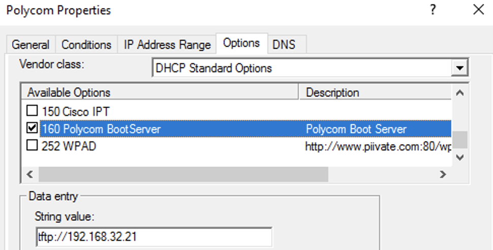
Polycom phones utilize DHCP option 160 to find a provisioning server. The contents of option 160 must be in string format. (e.g. tftp://192.168.1.10)
For time synchronization, DHCP option 42 must be set.

They also use DHCP option 002 to get the time offset. 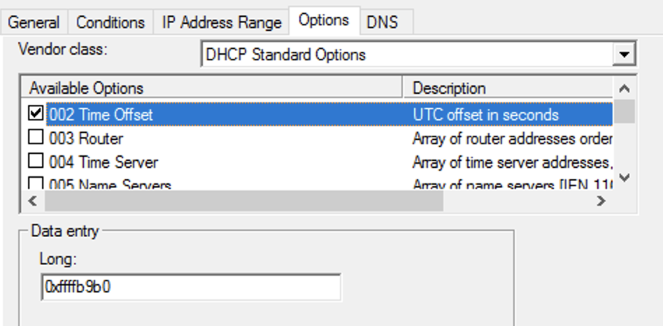
I use software called Tftpd64 to create a tftp server on my windows PCs. I tell it which folder I dump all my config files into.
when the phone boots, it will look for [mac address].cfg, if it can’t find that, it will look for [mac address]-web.cfg, then 000000000000.cfg.
000000000000.cfg is supposed to be the catchall for phone provisioning. It should not contain any actual phone provisioning commands, it only helps the phone point to other configuration files.
Polycom recommends using XML Notepad by Microsoft to edit these files.
000000000000.cfg defines the following settings before the phone boots:
This is an example deployment scenario:
The following settings are important for a FreePBX Deployment
msg.mwi.1.callBackMode=”contact” – This is part of the fix for the voicemail button. By default it is set to “register”, but FreePBX requires SIP phones to call a number to get voicemail
voIpProt.SIP.AlertInfo.1.value=”Auto Answer” – When a user dials *80[ext], typically the phone will autoanswer. This is known as page/intercom mode. Special SIP headers are sent by FreePBX so the phone recognizes a page from a regular call. Setting this will make the phone aware of a page
voIpProt.SIP.AlertInfo.1.class=”ringAutoAnswer” – your polycom phone has profiles that define what ringtone to use, how many times to ring, and to auto answer. This setting will tell the phone to auto answer if the SIP.AlertInfo field equals “Auto Answer”
attendant.resourceList.1.label=”Page All” – I have my main page group set to 900 in FreePBX -> Applications -> Paging and Intercom -> Page Group. These commands will create a softkey button to page all phones in page group 900.
attendant.resourceList.1.address=”900″
attendant.resourceList.1.type=”normal”
msg.mwi.1.subscribe=”[ext]” – enter your sip extension here to get the mailbox to work
msg.mwi.1.callBack=”*98[ext]” – enter *98 and your sip extension here. This is the number that is called when the voicemail button is pressed.
What isn’t shown
AX-SUB28SWC-6V – subaru/toyota/lexus/scion use a standard 28 pin connector.
This connector has the capability to provide:
However not all features are available in the WRX, as some pins are missing.
The AX-SUB28SWC-6V requires modification to work with the WRX.
This is the only option available for retaining steering wheel control and backup cam. Out of the entire install, this part gave me the most trouble because the connector had to be re-pinned.
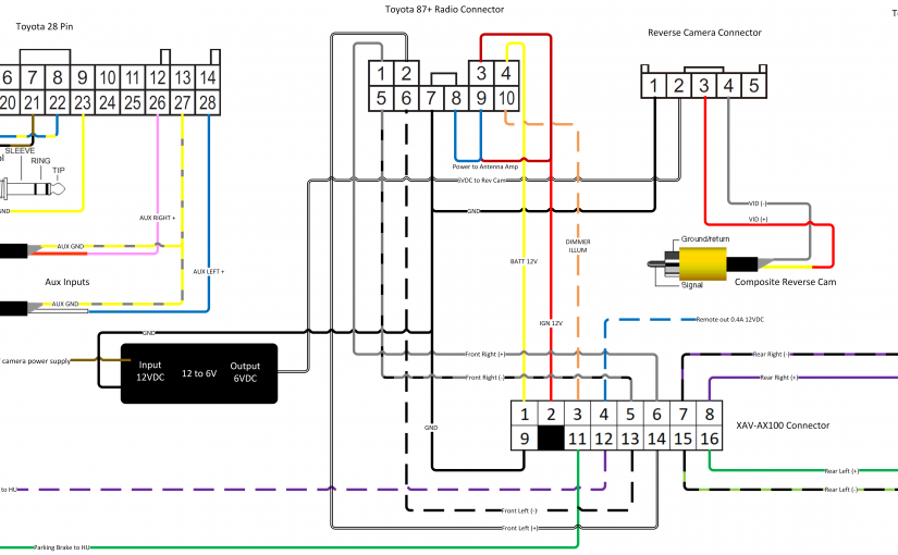
Luckily I made a diagram that should help you figure out what goes where.
When it was all said and done, I only needed 5 of the pins in the 28 pin connector:
Also note: the Metra connector is fragile, do not force in.
The black connector end of the AX-SUB28SWC typically connects to a Metra Axxess ASWC-1 can be chopped off, because the XAV-AX100 is capable of reading the signals directly from the steering wheel via pins 21-23 on the 28 pin connector
Pins 21-13 can be soldered/crimped directly to the 3.5mm jack, then connected to the “remote” port on the XAV-AX100 (see wiring diagram)
the WRX backup cam requires 6V. The AX-SUB28SWC-6V includes a 12 to 6V converter for this purpose.
When shifted into reverse, pin 2 of the 28 pin connector is given 12V. That 12V is sent into the 12to6 adapter, and 6V gets sent out to power the reverse camera.
The 2018 WRX Premium uses a 5 pin connector for backup camera video and power, instead of the 28 pin (as is common in other Toyotas)
If yours uses the 5 pin, there is no known wiring harness you can buy to adapt the backup camera. We must make our own with breadboard jumpers.
Take 5 of those wires, and cut and strip them, the bare wire side will be soldered to:
stick them into the OEM camera harness and tape (see wiring diagram for detailed info)
AX-SUBUSB2 Converts a standard male USB connection to the subaru connector found on the OEM harness. This allows you to use the OEM usb ports in your car, with an aftermarket stereo.
(This only works out of the box with WRX’s with a single USB port in center console)Newer WRXs have 2 USB ports and have a builtin USB hub. Since Android Auto/CarPlay is not compatible with USB hubs, a single Aux/USB combo module from 15-17 WRX can be swapped in, if needed. (video coming soon)
Metra 72-8104 – door speaker, minor modification to plastic adapter required to get proper fitment
Screws (3 per door). OEM screws that connect speaker to door, have too large of a head to accommodate the Metra 72-8104. Any hardware store will carry a screw with a smaller head that won’t interfere with the speaker adapter. (these are not machine screws, they have pointed tips, they go into the plastic inserts in the door)
Speaker Foam – Creates a seal between the speaker frame and plastic Metra adapter to prevent vibrations.
Dynamat (recommended) – Stick inside door panel, reduces vibrations, gives door speakers more bass, and makes interior quieter
After you get everything running you’ll want to do a couple things:

Quick tip. Avoid running a positive wire from the tail light harness to your head unit for a backup camera
this pink wire in the driver side kick panel cover is the wire that provides 12V when the car is in reverse. Plug this into your head unit to automatically bring up the reverse camera
its position in the harness is bottom left
here is a photo from the wiring diagram
 Here is a photo from further back